
Challenger V6-3.5L (2009)
Keyless Entry Module: Description and Operation
Passive Entry Module - Operation
OPERATION
The microprocessor in the Passive Entry Module (PEM) contains the logic circuits and controls all of the features of the Passive Entry (PE) and Keyless
Go (KG) systems. The PEM receives battery voltage on a fused B(+) circuit and is grounded at all times through a hard wired remote ground point.
These connections allow the PEM to operate regardless of the ignition switch position and with the IOD fuse removed.
The PEM has sufficient driver outputs to power a number of Low Frequency (LF) Radio Frequency (RF) antennas located within the vehicle, which it
uses to communicate with up to eight different FOB with Integrated Key (FOBIK) units that have been programmed to the vehicle. The FOBIK units
communicate with the PEM using Very High Frequency (VHF) RF communication on a frequency of 434 MegaHertz (MHz) using digital
Frequency-Shift Keying (FSK) modulation, and uses faster data rates for the PE functionality only.
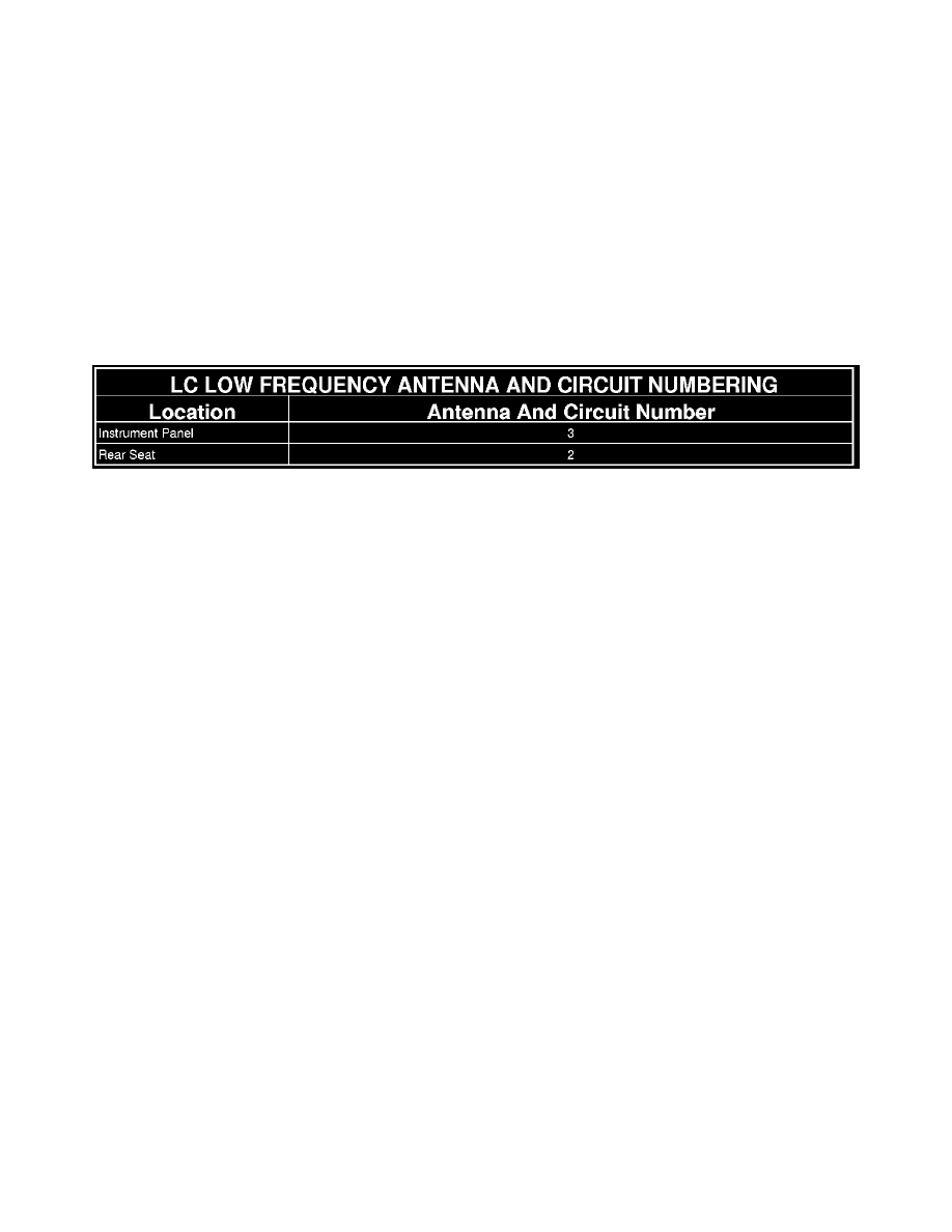
The number of antennas and the specific antenna locations are designed to ensure complete vehicle interior coverage. The LF antennas are each
numbered and connected to the PEM on dedicated and sequentially numbered circuits. This arrangement allows the PEM to localize the positions of
transmitting FOBIK units using a triangulation strategy. See the LC Low Frequency Antenna And Circuit Numbering table.
The location of a valid FOBIK is critical to the PE and KG features that the PEM will allow. The PEM has the ability to distinguish that a FOBIK is
inside, outside or within the trunk of the vehicle. Inside of the vehicle is defined as anywhere within the passenger compartment and up to 10 centimeters
(4 inches) from the exterior surfaces of the vehicle. Trunk is defined as anywhere within the trunk compartment of the vehicle.
Outside of the vehicle is defined as anywhere within about 10 centimeters (4 inches) and up to about 2 meters (6.5 feet) from the exterior surfaces of the
vehicle, but is further differentiated by zones. The PEM identifies the zone in which the valid FOBIK is located as the active zone, which determines
which vehicle aperture becomes accessible. The PEM will not respond to an input from a zone that is not active.
When the PEM microprocessor detects a PE input or KG request, the system program logic challenges the FOBIK to identify whether it is a valid key. If
a valid key is detected through the response from the FOBIK, then necessary electronic message commands to other electronic modules in the vehicle
will be sent by the PEM to enable or disable the vehicle starting system.
The PEM uses On-Board Diagnostics (OBD) and communicates with other modules in the vehicle as well as with a diagnostic scan tool using the
Controller Area Network (CAN) data bus. This method of communication is used by the PEM to acquire vehicle configuration data, including customer
programmable features. The PEM communicates with the Wireless Ignition Node (WIN) (also known as the Wireless Control Module/WCM or Sentry
Key REmote Entry Module/SKREEM), the Electro Mechanical Instrument Cluster (EMIC) (also known as the Cab Compartment Node/CCN), the
Powertrain Control Module (PCM) and the Totally Integrated Power Module (TIPM) (also known as the Forward Control Module/FCM) using the CAN
data bus.
The PEM microprocessor monitors all of the PE and KG system circuits, then sets active and stored Diagnostic Trouble Codes (DTC) for any monitored
system faults it detects. The PEM will also send electronic message requests to the EMIC for the display of certain textual warning messages related to
PE and KG system operation in the Electronic Vehicle Information Center (EVIC).
The hard wired inputs and outputs of the PEM may be diagnosed using conventional diagnostic tools and procedures. Refer to the appropriate wiring
information. However, conventional diagnostic methods will not prove conclusive in the diagnosis of the PEM electronic controls or the communication
between modules and other devices that provide some features of the PE and KG systems. The most reliable, efficient and accurate means to diagnose
the PEM or the electronic controls and communication related to PE or KG system operation requires the use of a diagnostic scan tool. Refer to the
appropriate diagnostic information.