
Challenger V8-5.7L (2010)
the CCN. For further diagnosis of the tachometer or the CCN circuitry that controls the gauge, See: Testing and Inspection. The tachometer is serviced as
a unit with the instrument cluster.
The gauges are diagnosed using the CCN self-diagnostic test See: Testing and Inspection. Proper testing of the CAN data bus and the electronic data bus
message inputs to the CCN that control each gauge require the use of a diagnostic scan tool. Refer to the appropriate diagnostic information.
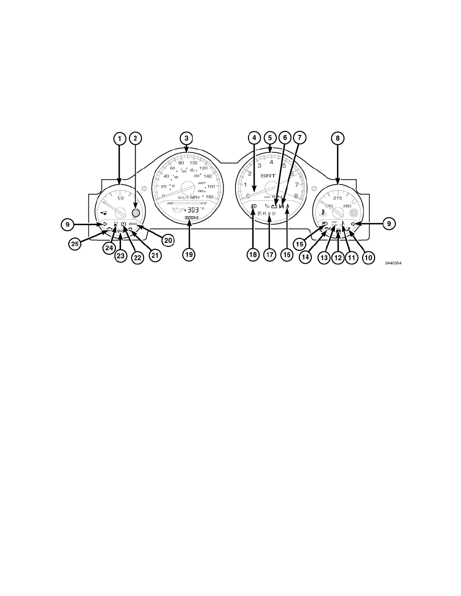
Instrument Cluster Indicators - Description
DESCRIPTION
NOTE: The Electronic Stability Control (ESC) may also be referred to as Electronic Stability Program (ESP) depending on the vehicle model
year and configuration. Certain components may also reference ESP, ESC, or use the traction control symbol.
The instrument cluster assembly has provisions for up to 19 International Control and Display Symbol icon indicators, as well as 4 analog gauges,See:
Gauge Pack - Description standard on all models, that are all controlled by the Cab Compartment Node (CCN). Some of the indicators are automatically
configured when the CCN is connected to the vehicle's electrical system for compatibility with certain optional equipment or equipment required for
regulatory purposes in certain markets. While each instrument cluster may have provisions for indicators to support every available option, the
configurable indicators will not function in vehicles that do not have the equipment that an indicator supports.
Each indicator in the instrument cluster, except those located within a VFD unit, is illuminated by a dedicated Light Emitting Diode (LED) that is
soldered onto the CCN electronic circuit board. Cluster illumination is accomplished by several dimmable LED units, which illuminate each of the gauge
dial faces for visibility when the exterior lighting is turned ON. These LED units as well as the CCN module are serviced only as a complete unit with
the instrument cluster and, if damaged or ineffective, the entire instrument cluster assembly must be replaced. The cluster lens and the cluster hood and
mask unit are the only components of the instrument cluster assembly that can be serviced separately.
The instrument cluster includes provisions for the following indicators:
-
Airbag Indicator (11)(10)
-
Ajar Indicators - text in odometer / EVIC display (6)(19)
-
Antilock Brake System (ABS) Indicator (9)(23)
-
Brake Indicator (12)(20) - text only for U.S. market, icon only for markets outside U.S.
-
Change Oil Indicator - textual message in odometer / EVIC display (6)(19)
-
Charging Indicator (23)(6)
-
Cruise Indicator (1)(4)
-
Electronic Stability Program (ESP)/Brake Assist System (BAS) Indicator (10)(13)
-
Electronic Throttle Control (ETC) Indicator (21)(7)
-
Engine Coolant Temperature Indicator (8)(11)
-
Front Fog Lamp Indicator (3)(18) - with optional front fog lamps only
-
Fuel Saver Indicator- ECO nomizer (ECO) (6)(19) - textual message in odometer display or in EVIC if equipped.
-
Gas Cap Indicator - textual message in odometer / EVIC display (6)(19)
-
Gear Selector Indicator (17)(17) - with automatic transmission only
-
High Beam Indicator (16)(15)
-
Low Fuel Indicator (2)(24)
-
Low Oil Pressure Indicator (25)(14)
-
Malfunction Indicator Lamp (MIL) (24)(25)- only on domestic market vehicles
-
No Bus Indicator - textual message in odometer / EVIC display (6)(19)
-
No Fuse Indicator - textual message in odometer / EVIC display (6)(19)
-
Seat Belt Indicator (18)(16)