
Challenger V8-5.7L (2010)
Clockspring Assembly / Spiral Cable: Description and Operation
Clockspring - Description
DESCRIPTION
WARNING: To service any component of the Steering Column Control Module (SCCM), the entire assembly must be removed from the
column. This must be done due to the clockspring passing through the assembly and into the self docking connector. Failure to
remove the assembly could damage the pins of the clockspring and prevent the airbag system from operating properly Failure to
follow these instructions may result in possible serious or fatal injury.
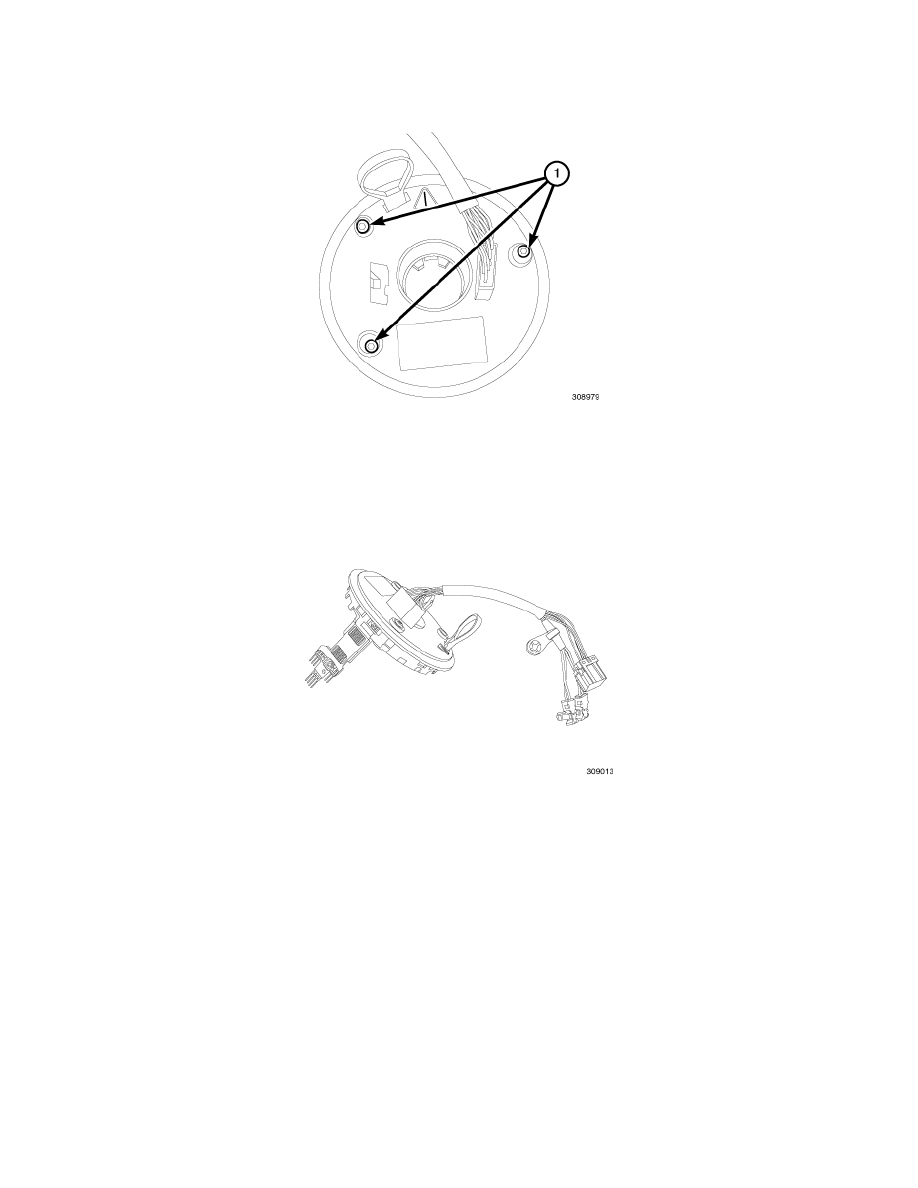
The clockspring assembly is secured with three screws (1) onto the top of the Steering Column Control Module (SCCM) See: Accessories and Optional
Equipment/Steering Mounted Controls Communication Module/Description and Operation/Steering Column Control Module - Description near the top
of the steering column behind the steering wheel.
The clockspring consists of a flat, round molded plastic case. Within the plastic case is a spool-like molded plastic rotor with a hub. The surface of the
rotor hub has a large center hole. Within the plastic case, and wound around the rotor spool, is a long ribbon-like tape that consists of several thin copper
wire leads sandwiched between two thin plastic membranes. The outer end of the tape terminates at the connector terminals that align themselves into the
SCCM self-docking connector that faces the instrument panel, while the inner end of the tape terminates at the pigtail wires and connector receptacles on
the hub of the clockspring rotor that face the steering wheel.