
Challenger SRT-8 V8-6.1L (2009)
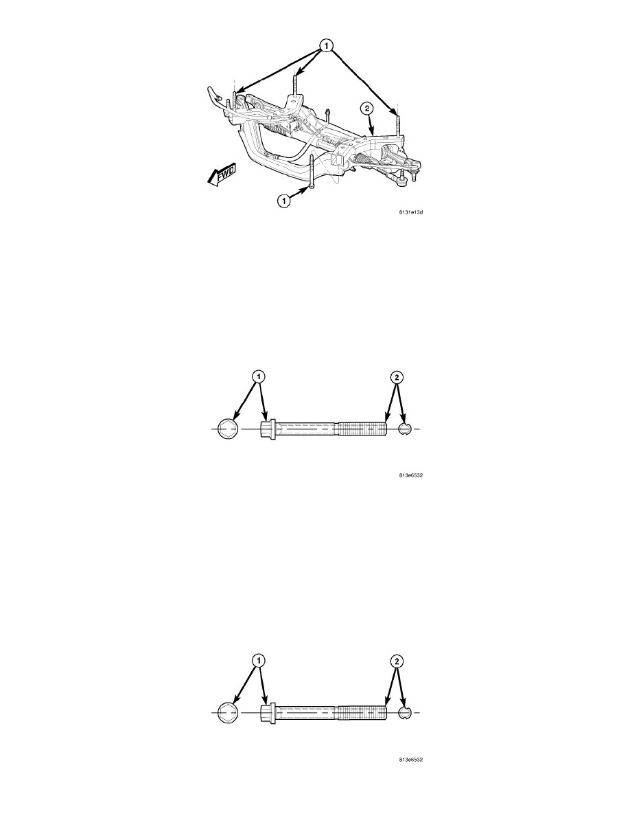
1. Loosen the four bolts (1) fastening the engine cradle (2) to the frame just enough to allow movement of the cradle.
2. Shift cradle as necessary to bring camber or caster into specifications. When shifting cradle, use care not to move other angles (camber or caster)
that are within specifications, out of specifications.
3. Tighten the four bolts (1) fastening the engine cradle (2) to the frame to specifications.
4. Jounce the rear, then front of the vehicle an equal amount of times.
5. Measure camber and caster. If camber and caster are within specifications, proceed to TOE. If camber or caster cannot be brought into
specifications, perform the ADJUSTMENT BOLT PACKAGE INSTALLATION below.
ADJUSTMENT BOLT PACKAGE INSTALLATION
The adjustment bolt package contains 2 special bolts (1). These bolts can be identified by the offset grooves cut into the thread section (2). These bolts
are designed to replace the inboard mounting bolts of the lower control arm and tension strut. Each bolt allows approximately 0.3 degrees of movement.
To adjust camber only, use both bolts, one at the tension strut and the other at the lower control arm. To adjust caster only, use one bolt at the tension
strut only.
1. Raise the vehicle by the frame until the tires are not supporting the weight of the vehicle.
2. Remove the belly pan as necessary. See: Body and Frame/Exterior Moulding / Trim/Underbody Cover/Service and Repair/Belly Pan - Removal
3. Lower control arm bolt only:
a. Remove the screws fastening the heat shields covering the stabilizer bar bushing retainers to the cradle. Remove the heat shields.
b. Remove the four bolts (two each) fastening the stabilizer bar bushing retainers to the cradle.
c. Swing the stabilizer bar rearward and down out of the way of the control arm mounting bolts.