
Charger V6-3.5L (2009)
NOTE: These step's are critical to the alignment of the ACC to the vehicle, make sure that you have the correct measurement and the aiming
board is in the correct position.
CAUTION: Ensure that there are no reflective surfaces or objects within 2 m (6.56 ft.) behind the aiming board. These objects may cause an
error during the aiming process and be interpreted as a board misalignment.
1. Position the vehicle on a level/flat surface.
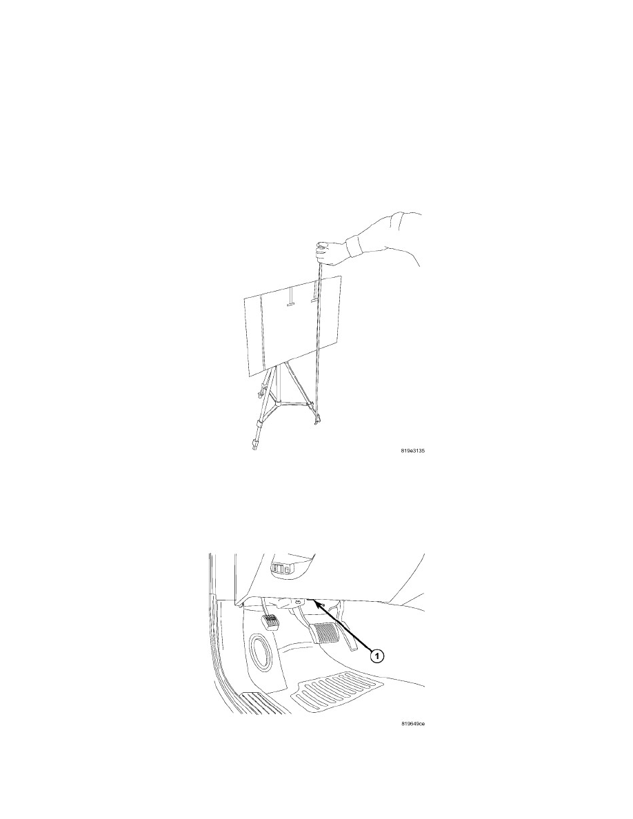
2. Place the aiming board (4) (Special Tool No. 9965) and tripod (5) (Special Tool No. 9649) 4 meters (2) (157.5 inches) from the front of the ACC
module and 90 degrees to the front of the vehicle. Ensure that there are no reflective surfaces or objects within 2 m (6.56 ft.) behind the aiming
board. Measure from the front of the ACC module grille area to the aiming board.
3. Sight through the V-notch (1) in the upper edge of the aim board to align and center the board to the centerline marks on both the windshield and
the rear glass.
4. Verify center line marks on both the windshield and the rear glass of vehicle with V-notch in board by looking from the rear of vehicle.
5. Adjust the tripod so that the top edge of the aiming board is level at BOTH CORNERS. For setting the board height dimensions, See: Cruise
Control/Cruise Control Module/Specifications.
CALIBRATION PROCEDURE
1. Turn the ignition switch to the ON position.
2. Connect a scan tool to the Data Link Connector (DLC) (1) below the driver side end of the instrument panel (2).
3. Obtain vehicle information, select ECU View from the Home Screen.
4. The Scan tool will then show a list of all ECU's available on the vehicle.