
Charger V6-3.5L (2009)
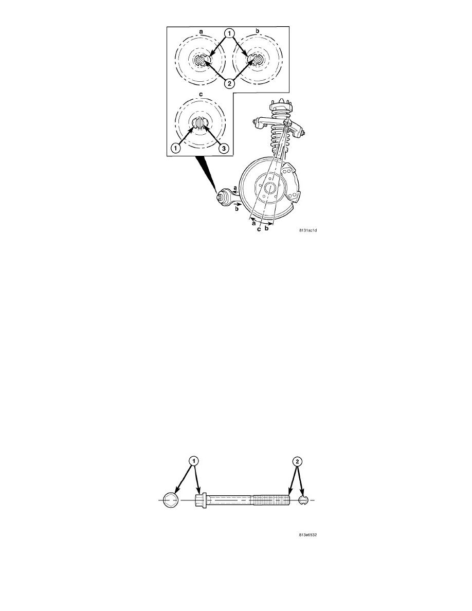
NOTE: The original (non-grooved) mounting bolt (3) lies through the center of the hole (1), between the "bat wings" as shown in (c).
6. Caster Adjustment - The adjustment bolts are designed to work in conjunction with "bat wings" that are formed into the engine cradle (1) allowing
for lower control arm movement approximately 0.3° in either direction.
-
To achieve more positive caster, refer to (a) in the figure. Move the lower control arm in the desired direction, then insert the adjustment bolt
(2) with a washer installed through the bat wing hole in the engine cradle (1) and the round hole in the bushing inner metal.
-
To achieve more negative caster, refer to (b) in the figure. Move the lower control arm in the desired direction, then insert the adjustment bolt
(2) with a washer installed through the bat wing hole in engine cradle (1) and round hole in the bushing inner metal.
7. Start a NEW nut on the end of the mounting bolt by hand, then while holding the head of the bolt stationary, install the nut. Do not tighten the
nut at this time.
8. Rear adjustment bolt only - Reinstall the steering gear and heat shields. See: Steering/Steering Gear/Service and Repair/Steering Gear - Installation
9. Lower the vehicle to curb position. Jounce the rear, then the front of the vehicle an equal amount of times.
10. Using a crowfoot wrench, tighten the adjustment bolt nut to 176 Nm (130 ft. lbs.) while holding the bolt stationary. A socket on the end of a
breaker bar works well for holding the rear bolt stationary with the steering gear is installed.
11. Measure camber and caster. If camber and caster are not within specifications, inspect the suspension components for any signs of damage or
bending. If camber and caster (and cross-camber and cross-caster) are within specifications, proceed with TOE to check and adjust toe.
12. Install the belly pan. See: Body and Frame/Exterior Moulding / Trim/Underbody Cover/Service and Repair/Belly Pan - Installation
ADJUSTMENT BOLT PACKAGE INSTALLATION - REAR-WHEEL-DRIVE (RWD)
NOTE: Adjustment bolts for AWD and RWD are not interchangeable.
The adjustment bolt package contains 2 special bolts (1). These bolts can be identified by the offset grooves cut into the thread section (2). These bolts
are designed to replace the inboard mounting bolts of the lower control arm and tension strut. Each bolt allows approximately 0.3 degrees of movement.