
Charger V6-3.5L (2009)
9. Position vehicle on an alignment rack/drive-on lift.
10. Tighten lower shock mounting bolt (3) to 174 Nm (128 ft. lbs.).
11. Perform wheel alignment. See: Alignment/Service and Repair
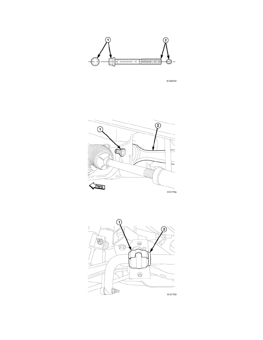
CAUTION: If the control arm engine cradle bolt is a wheel alignment adjustment bolt (lengthwise grooved shaft (2)), be sure to only tighten
the nut. Do not rotate the bolt head (1) or damage to the bushing will occur.
12. Once camber is found to be within specifications, using a crowfoot wrench, tighten lower control arm cradle bolt nut (1) to 176 Nm (130 ft. lbs.)
while holding the bolt stationary.
CAUTION: Because of stabilizer bushing outer shape, it is very important to install bushings in position discussed in following step.
13. Utilizing slit in bushing, install stabilizer bar bushing (1) against locating collar on stabilizer bar (2) as shown. Make sure slit in bushing is
positioned toward rear of vehicle.