
Charger V8-5.7L (2008)
-
(3) Spherical Washer
-
(4) Thrust Bearing
-
(5) Sleeve 9361-4 (RWD)
-
(5) Sleeve 9361-5 (AWD - Left Side)
-
(5) Sleeve 9361-6 (AWD - Right Side)
NOTE: When installing thrust bearing on Remover, be sure to place hardened side against nut. Place bearing outer cage against
stationary component.
NOTE: It is important to use appropriate Sleeve on Remover to provide proper Tool-to-Knuckle contact. RWD sleeve can be used on either
side while AWD knuckles require specific left or right side Sleeves.
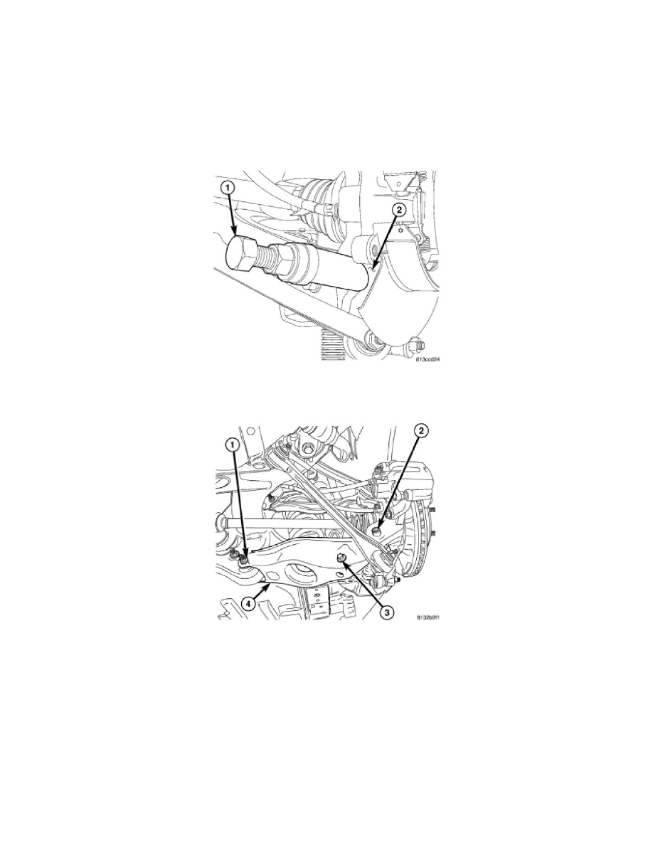
7. Thread Remover Bolt 9361-3 (1) into tapped knuckle sleeve.
8. Rotate Nut down, matching Sleeve angled end with angled face of knuckle.
9. Continue to rotate Nut until knuckle sleeve is removed from knuckle. Discard knuckle sleeve; replace it with new upon installation.
10. Remove bolt and nut (1) fastening spring link (4) to crossmember.
11. Remove spring link (4).
Spring Link - SRT8
SPRING LINK - SRT8
1. Access and remove rear brake rotor on side of repair. See: Brakes and Traction Control/Disc Brake System/Brake Rotor/Disc/Service and
Repair/Removal and Replacement/Brake Rotor - Removal
2. Access and remove rear spring on side of repair. See: Suspension Spring ( Coil / Leaf )/Service and Repair/Rear Spring - Removal