
Charger V8-5.7L VIN H (2007)
18. Raise the vehicle by the frame until the tires are not supporting the weight of the vehicle.
19. Remove the belly pan as necessary.
20. Lower control arm bolt only:
a. Remove the screws fastening the heat shields covering the stabilizer bar bushing retainers to the cradle. Remove the heat shields.
b. Remove the four bolts (two each) fastening the stabilizer bar bushing retainers to the cradle.
c. Swing the stabilizer bar rearward and down out of the way of the control arm mounting bolts.
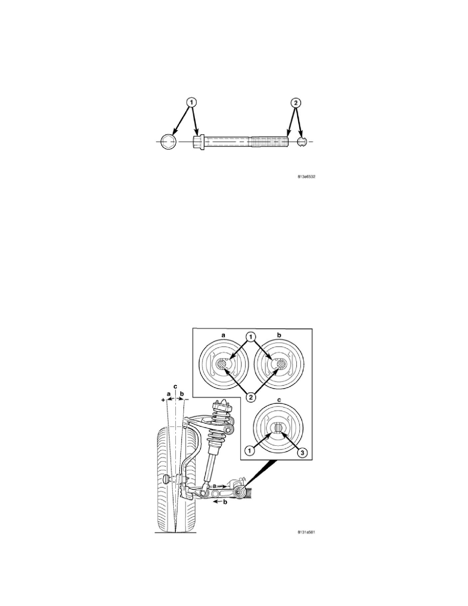
CAUTION: Wheel alignment adjustment bolts have offset grooves cut into the length of the bolt (2). If removing or installing lower
control arm or tension strut mounting bolts that have these grooves, DO NOT ROTATE THE BOLT. To remove the bolt, hold the bolt
head stationary and rotate the nut, then slide the bolt straight out of the bushing. This is necessary to avoid damaging the bat wings in the
bushing inner metal or cradle.
21. Hold the head of the control arm or tension strut mounting bolt stationary and remove the nut. Slide the bolt straight out of the bushing and
discard.
CAUTION: When installing an adjustment bolt, be sure to install it in the correct direction. Lower control arm bolts must be installed
from the rear-forward to avoid contact with the stabilizer bar upon installation. Tension strut bolts must be installed from the
front-rearward.
NOTE: The grooves on the adjustment bolts are off-center forcing the bolt to be installed in one of two ways depending on whether more
positive or negative camber or caster is necessary. The Bolts must be rotated 180° to achieve either more positive or negative camber or
caster. DO NOT force the adjustment bolt.
NOTE: The original (non-grooved) mounting bolt (3) lies through the center of the hole (1), between the "bat wings" (c).
22. Camber Adjustment - The adjustment bolts are designed to work in conjunction with "bat wing" holes that are formed into the inner metal of the
lower control arm bushing (1) allowing for lower control arm movement approximately 0.3° in either direction.
-
To achieve more positive camber, refer to (a) in the figure. Move the control arm or tension strut in the desired direction, then insert the