
Colt Vista AWD L4-1795cc 1.8L SOHC (1993)
Idle Position Switch: Testing and Inspection
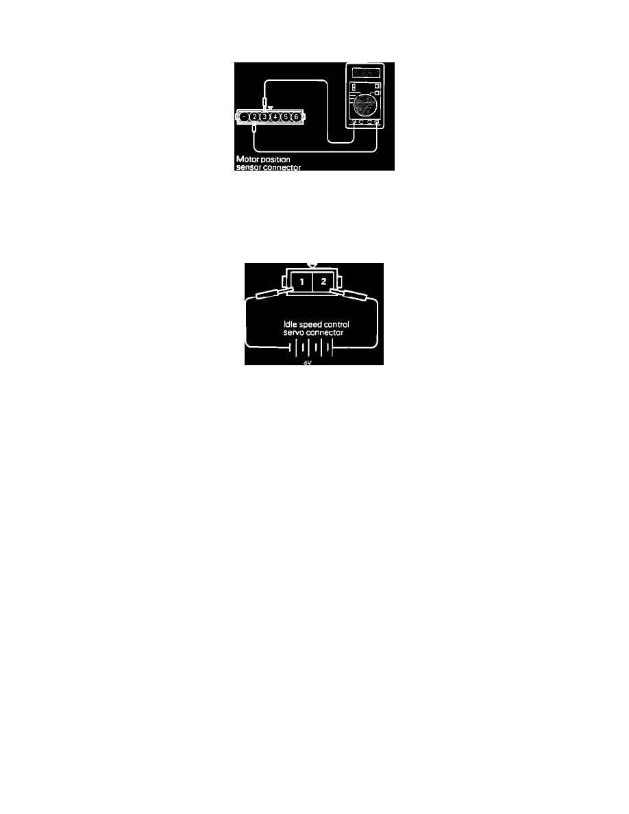
1.
Disconnect the Motor Position Sensor connector.
Checking The Motor Position Sensor Resistance
2.
Using an ohmmeter, check the resistance between terminals # 2 and # 3.
Refer to SPECIFICATIONS/ELECTRICAL.
3.
Disconnect the Idle Speed Control Servo connector.
Checking The Operation
4.
Connect a 6 volt power source to terminals # 1 and # 2 of the ISC Servo.
CAUTION: Apply only 6 volts or lower voltage. Application of a higher voltage could cause the servo gears to lock.
5.
While voltage is being applied to the servo, measure the resistance between terminals # 3 and # 5 of the Motor Position Sensor.
Resistance should change smoothly with the expansion and contraction of the ISC Servo plunger.
Refer to SPECIFICATIONS/ELECTRICAL.
6.
If there is a deviation in the test results, or if resistance does not change smoothly, replace the ISC Servo assembly.
Refer to COMPONENT REPLACEMENT AND REPAIR PROCEDURES.