
D150 1/2 Ton Pickup 2WD L6-225 3.7L VIN H 1-bbl (1983)
Ammeter Gauge: Description and Operation
The ammeter is an instrument used to indicate current flow into and out of the battery. When electrical accessories in the vehicle draw more current
than the alternator can supply, current flows from the battery, and the ammeter indicates a discharge ( - ) condition. When electrical loads of the vehicle
are less than alternator output, current is available to charge the battery, and the ammeter indicates a charge (+) condition. If battery is fully charged, the
voltage regulator reduces alternator output to meet only immediate vehicle electrical loads. When this happens, ammeter reads zero.
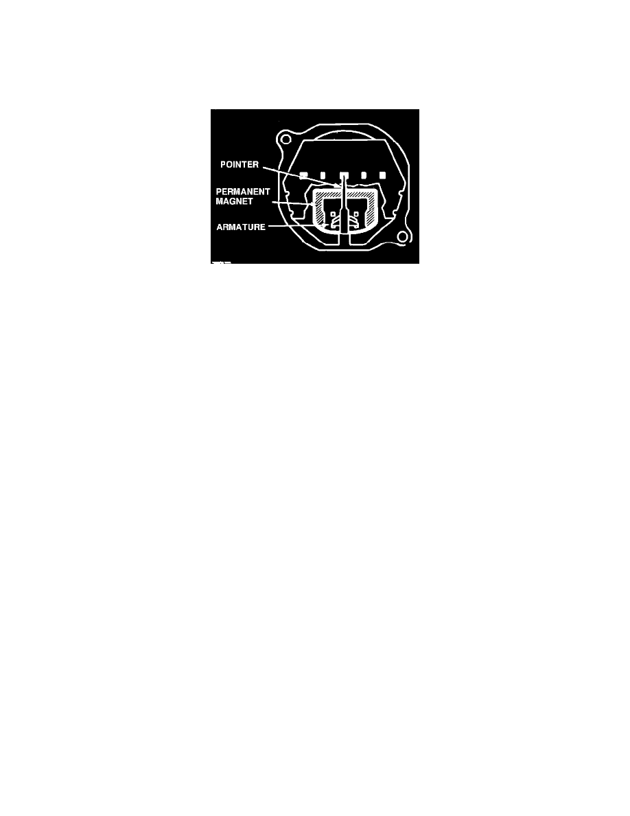
Fig. 1 Typical conventional type ammeter
CONVENTIONAL AMMETER
A conventional ammeter must be connected between the battery and alternator in order to indicate current flow. This type ammeter consists of a frame
to which a permanent magnet is attached. The frame also supports an armature and pointer assembly. Current in this system flows from the alternator
through the ammeter, then to the battery or from the battery through the ammeter into the vehicle electrical system, depending on vehicle operating
conditions.
When no current flows through the ammeter, the magnet holds the pointer armature so that the pointer stands at the center of the dial. When current
passes in either direction through the ammeter, the resulting magnetic field attracts the armature away from the effect of the permanent magnet, thus
giving a reading proportional to the strength of the current flowing.
Troubleshooting
When the ammeter apparently fails to register correctly, there may be trouble in the wiring which connects the ammeter to the alternator and battery or
in the alternator or battery itself.
To check the connections, first tighten the two terminal posts on the back of the ammeter. Then, following each wire from the ammeter, tighten all
connections on the ignition switch, battery and alternator. Chafed, burned or broken insulation can be found by following each ammeter wire from end to
end.
All wires with chafed, burned or broken insulation should be repaired or replaced. After this is done, and all connections are tightened, connect the
battery cable and turn on the ignition switch. The needle should point slightly to the discharge ( - ) side.
Start the engine and run slightly above idling speed. The needle should move slowly to the charge side (+).
If the pointer does not move as indicated, the ammeter is out of order and should be replaced.
SHUNT TYPE AMMETER
The shunt type ammeter is actually a specifically calibrated voltmeter. If it connected to read voltage drop across a resistance wire (shunt) between the
battery and alternator. The shunt is located either in the vehicle wiring or within the ammeter itself.
When voltage is higher at the alternator end of the shunt, the meter indicates a charge (+) condition. When voltage is higher at the battery end of the
shunt, the meter indicates a discharge ( - ) condition. When voltage is equal at both ends of the shunt, the meter reads zero.
Troubleshooting
Ammeter accuracy can be determined by comparing reading with an ammeter of known accuracy.
1. With engine stopped and ignition switch in RUN position, switch on headlamps and heater fan. Meter should indicate a discharge ( - ) condition.
2. If ammeter pointer does not move, check ammeter terminals for proper connection and check for open circuit in wiring harness. If connections and
wiring harness are satisfactory, ammeter is defective.
3. If ammeter indicates a charge (+) condition, wiring harness connections are reversed at ammeter.