
D50/Power Ram 50 L4-2300cc 2.3L DSL (1984)
Generator: Testing and Inspection
Charging Voltage Test
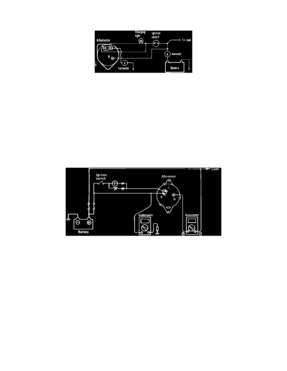
Fig. 1 Alternator charging voltage test connection. Exc. Battery voltage sensing type alternator
Exc. Battery Voltage Sensing Type
1.
With ignition switch in the "Off" position, disconnect battery positive cable, then connect an ammeter between cable and battery positive post.
2.
Connect a voltmeter between alternator terminal L and ground. Ensure voltage reading is zero. If a reading or needle deflection is indicated on the
voltmeter, either the alternator or alternator wiring is defective.
3.
Place ignition switch in the "On" position, then note voltmeter reading. Voltmeter should indicate a reading considerably less than battery voltage.
If reading indicates battery voltage, the alternator may be defective.
4.
Connect jumper cable between battery positive post and battery positive cable, then start engine. This will prevent starting current from being
applied to ammeter.
5.
Remove jumper cable connected between battery positive post and cable, then increase engine speed to 2000 to 3000 RPM and note ammeter
reading. If reading is 5 amps or less (10 amps or less for 1987-88 models), note voltage reading. If reading is above 5 amps (10 amps or less for
1987-88 models), either continue to charge battery until reading drops to 5 amps or less (10 amps or less for 1987-88 models) or install a fully
charged battery. The charging current may also be limited by installing a {1/4} ohm resistor in series with the battery.
6.
Charging voltage should be as listed in the "Alternator and Regulator Specification Chart."
Fig. 2 Alternator charging voltage test connection. Battery voltage sensing type alternator
Battery Voltage Sensing Type
1.
With ignition switch in the "Off" position, disconnect battery ground cable and connect a digital voltmeter between alternator S terminal, and
ground.
2.
Disconnect alternator output wire from alternator B terminal, then connect a DC ammeter in series between the B terminal and the disconnected
output wire. Connect positive lead of ammeter to B terminal. Connect negative lead to the disconnected output wire.
3.
Set engine tachometer and reconnect battery ground cable.
4.
Place ignition switch in the "On" position and note voltmeter. The reading should be equal battery voltage. If reading is 0, there is either an open
circuit in the wire between alternator S terminal and battery positive terminal or a blown fusible link.
5.
Start engine, keeping all accessories and lights off. Run engine at a constant 2500 RPM and read voltmeter when alternator output current drops to
10 amps or less. Voltage reading should be as listed in the "Alternator and Regulator Specification Chart."