
D50/Power Ram 50 L4-2350cc 2.4L SOHC (1992)
2. Using an ohm meter, check for continuity between ECU harness terminal 101 and ground.
Continuity
Should exist.
3. Using an ohm meter, check for continuity between ECU harness terminal 106 and ground.
Continuity
Should exist.
If any of the previous tests produce unsatisfactory results, the harness will need to be repaired or replaced. Once repairs have been completed, road
test the vehicle to confirm that the repair has corrected the problem.
If the same problem reoccurs, it is possible that there is an intermittent failure of the component or the ECU. Check for looseness at all harness
junctions and test for an intermittent failure.
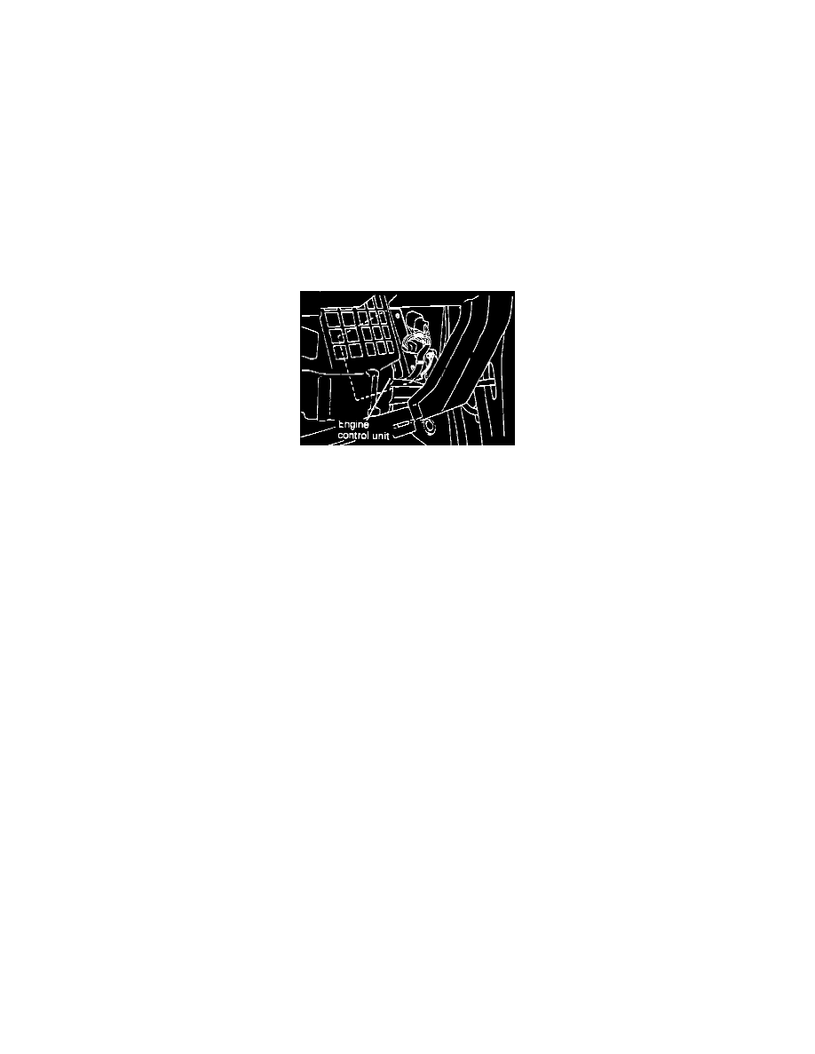
Electronic Control Unit (ECU)
Engine Control Module (ECM) Location
To test the Electronic Control Unit (ECU), located to the right of the glove box, proceed as follows:
NOTE: Diagnostic memory is erased if the battery or the ECU connector is disconnected. Do not disconnect the battery before the trouble codes
are completely read. If a sensor connector is disconnected with the ignition switch turned on, the diagnosis code is memorized. In this case,
disconnect the battery negative terminal for 15 seconds or more, and all diagnostic memory will be erased.
1.
Using the procedures contained in ON-BOARD DIAGNOSTICS extract all malfunction codes. Diagnosis memory is erased if the battery or the
ECU connector is disconnected. Do not disconnect the battery before the trouble codes are completely read.
CAUTION: When battery voltage is low, trouble codes cannot be read. Be sure to check the battery for voltage and other conditions before
starting the test.
2.
Does the ECU output a steady 12 VDC at the check connector?
a. If not, and the ECU is suspected to be faulty, check the POWER AND GROUND CIRCUITS test to confirm that the ECU is being supplied
with power and ground.
b. If so replacement of the ECU is required.
NOTE: Before replacing a ECU that is found to be faulty, insure that no other condition exists that will damage the new unit. This can be best done
by testing the inputs and outputs to the ECU for over voltage/inappropriate power readings or grounds. Use the image in CHASSIS
ELECTRICAL DIAGRAMS and the individual component testing procedures to identify the correct readings for each pin. Check all pins (at the
harness with the ECU removed) that supply a signal to the ECU, for their correct readings and check all other pins to insure that there are no
uncalled for voltage readings or grounds present.
3.
Compare all the remaining codes to the following list and perform the required inspections called for in each of the categories that are affected by a
code.
Check power supply for:
1. Faulty battery.
2. Faulty fusible link.
3. Faulty fuse.
4. Check for faulty body ground.
Check Fuel supply for:
1. Damaged fuel line.
2. Clogged or damaged fuel filter.
3. Faulty fuel pump.
Check ignition system for:
1. Faulty spark plugs.