
D50/Power Ram 50 L4-2350cc 2.4L SOHC (1992)
Air Flow Meter/Sensor: Testing and Inspection
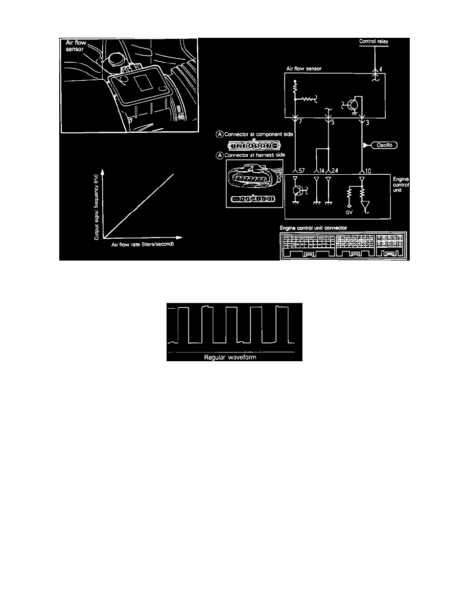
Air Flow Sensor Circuit
To test the Air Flow Sensor, located on the air cleaner housing proceed as follows.
Scope Pattern
OSCILLOSCOPE TESTING PROCEDURES:
1.
Run engine at idle speed.
2.
Engine coolant temperature should be at: 85-95~C (185-205~ F), with no electrical accessory loads on.
3.
Connect the input probe of the oscilloscope, to the pickup point shown in the circuit diagram, and check the wave form.
If scope pattern is not as depicted in image, continue with the rest of the test procedures before replacing the assembly.
FREQUENCY TESTING PROCEDURES:
1.
Warm engine. Coolant temperature should be at: 85-95~C (185-205~ F), with no electrical accessory loads on. Connect a Frequency counter
(HERTZ counter) between terminal 5 and 3 (do not remove the connector, instead insert a straight pin or needle from the back side of the
connector) of the Air Flow Sensor (AFS) connector.
Terminal 5: Sensor ground
Terminal 3: AFS output
2.
Measure the frequency across terminals 5 and 3.
Standard Values
40 to 60 Hz at 750 rpm
85 to 105 Hz at 2,000 rpm
Frequency increases as RPM increases
NOTE: If the air flow sensor fails, the intake air volume cannot be measured and as a result, normal fuel injection control is no longer available.
However, the vehicle will run using the pre-programmed value.