
D50/Power Ram 50 L4-2350cc 2.4L SOHC (1992)
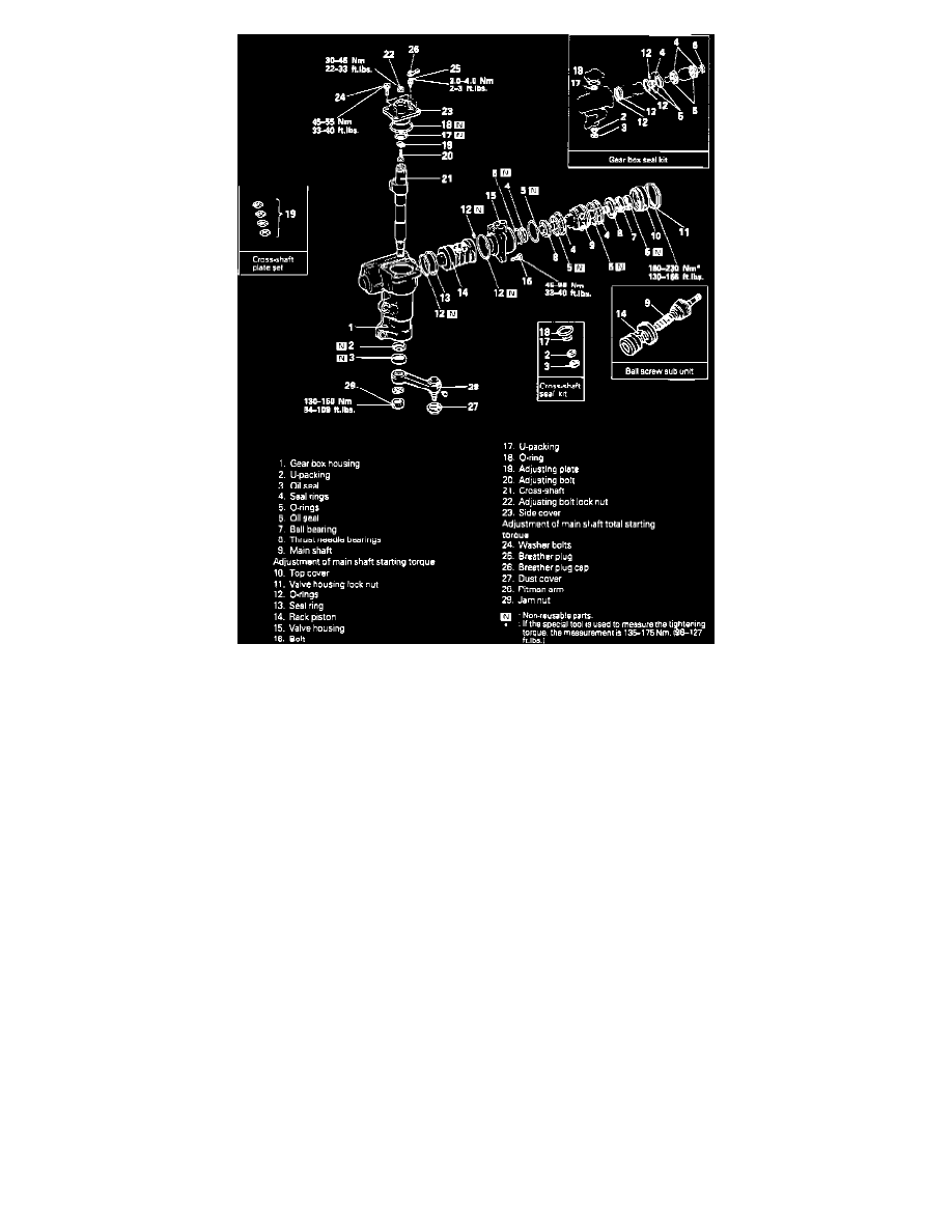
Fig. 1 Exploded view of Koyo Seiko power steering gear
1.
Remove adjusting locknut and the side cover attaching bolts, then turn adjusting bolt in 2 or 3 turns.
2.
With gear in Neutral position, tap bottom of cross shaft with rubber mallet to remove shaft with side cover.
3.
Screw in adjusting bolt on end of cross shaft to remove side cover. Use care not to lose any of the 33 needle bearing rollers.
4.
Remove O-ring, needle bearing, adjusting bolt, adjusting plate and U-packing from side cover. Do not remove U-packing at rear of needle
bearing if oil is not leaking from thread of adjusting bolt. Also, do not remove bleeder plug unless necessary.
5.
Remove valve housing nut using spanner wrench tool No. MB990852 or equivalent.
6.
Remove valve housing attaching bolts, then, while holding rack piston to avoid rotation, remove valve housing and rack piston. Do not hold
housing with rack piston down.
7.
Remove seal ring and O-rings from valve housing and rack piston.
8.
Remove valve housing top cover using wrench tool No. MB990853 or equivalent.
9.
Remove ball bearing and oil seal from top cover.
10.
Remove oil seal and U-packing from gear housing. Do not disassemble the needle bearing.
2 Wheel Drive
1.
Apply suitable grease to bearing surface of side cover needle bearing and install the 33 rollers.
2.
Apply suitable grease to bottom of side cover, then position new O-ring on the cover.
3.
Install adjusting bolt and plate into slot on top of cross shaft. Install plate with chamfered side toward cross shaft mating surface.
4.
Adjust cross shaft endplay to 0-.002 inch, using spacers as necessary.
5.
Install side cover onto cross shaft and tighten with adjusting bolt, then tighten locknut temporarily.
6.
Apply thin coat of suitable grease to gear housing U-packing and oil seal, then press them into housing.
7.
Apply thin coat of suitable grease to lip of valve housing oil seal, then press it into housing.
8.
Press ball bearing into top cover, then install thrust plate, needle roller bearing and second thrust plate into cover. Install thinner of the two
thrust plates on top cover side.
9.
Install and temporarily tighten the top cover.
10.
Using wrench tool No. MB990853 or equivalent and a spring scale, tighten top cover to a force of 14-19 lbs., then loosen top cover until torque
becomes 0 ft. lbs. Rotate input worm shaft and check for smooth operation.
11.
Measure starting torque using socket tool No. CT-1108 or equivalent, while turning input worm shaft, and note the value.