
D50/Power Ram 50 L4-2555cc 2.6L SOHC (1987)
6. Remove inner shaft from differential shaft carrier assembly.
7. Remove dust seal.
8. Reverse procedure to install noting the following:
a. Torque right drive axle to inner shaft assembly bolts to 37-43 ft. lbs.
b. On 1984 models, tighten shock absorber upper mounting nut until protrusion of stud above bottom of nut is 0.8 inch. On 1985-88 models,
tighten shock absorber upper mounting nut until protrusion of stud above top of nut is 0.5 inch for 1985 models or 0.27-0.31 inch for 1986
Ram 50 4 X 4 and 1987-88 Ram Raider. On 1987-88 Ram 50 4 X 4, tighten nut to end of threads. On all models, install jam nut and torque to
9-13 ft. lbs.
c. Mount knuckle and front hub assembly together and check drive axle endplay as follows: Install snap ring onto drive axle. Position dial
indicator on end of drive axle and turn drive axle in axial direction. Drive axle endplay should be 0.008-0.020 inch. Install proper spacer to
bring endplay into specification.
Disassembly
1. Remove boot bands from Birfield joint and double offset joint boots. Discard bands and replace with new bands at reassembly.
2. Remove circlip from double offset joint outer race.
3. Remove drive axle from double offset joint outer race.
4. Clean grease from outer race, then remove balls from cage.
5. Turn double offset joint cage 30 degrees from position at which balls were installed and push cage down toward Birfield joint until it is off inner
race.
6. Remove inner race snap ring, inner race and cage from end of drive axle.
7. Remove snap ring from drive axle, then remove double offset joint boot and Birfield boot. Tape end of drive axle so splines do not damage boots
as they are removed.
8. Remove dust cover. Do not disassemble Birfield joint.
9. Using suitable tool and press, remove bearing from inner shaft.
Inspection
1. Inspect outer race of double offset joint for excessive wear or damage.
2. Inspect bearing for damage to races.
3. Inspect drive axle and inner shaft for damage to splines.
4. Inspect drive and inner shaft for bending or other damage.
5. Inspect Birfield joint for damage to balls, water contamination, rust and other foreign material.
6. Inspect dust cover for proper shape and damage.
7. Inspect Birfield joint and double offset joint boots for deterioration, tears or cracks.
8. Inspect double offset joint inner race, balls and cage for damage, wear or rust.
Assembly
1. Press dust cover onto inner shaft.
2. Press inner bearing onto shaft using tool No. MD990560.
3. Press dust covers onto Birfield joints and double offset joints.
4. Apply grease to drive axle.
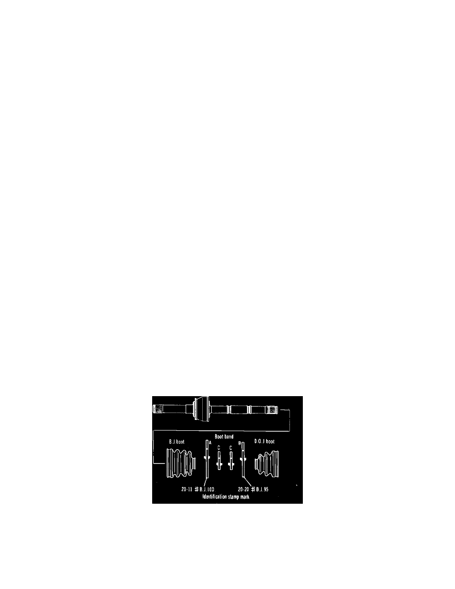
Fig. 7 Driveshaft boot and band identification
5. Install Birfield joint boot, all boot bands and double offset joint boot on drive axle and Birfield joint.
6. Install double offset joint cage onto drive axle with smaller diameter end of cage toward Birfield joint. Install snap ring, inner race and circlip onto
drive axle.
7. Apply grease to double offset joint inner race and cage, then fit balls into cage.
8. Apply 2-3 ounces of grease to outer race, then install race on drive axle.