
D50/Power Ram 50 V6-181 3.0L SOHC (1991)
57
RD/DB
Air Flow Sensor
58
DG/YL
ISC motor control
59
DG/BK
ISC motor control
60
DB/DG
Injector 3 ground
61
LG/WT
Injector 4 ground
62
BR/DB
Purge Solenoid Control
63
DB/DG
Control Relay control by ECU
64
LG/RD
Check engine light ground (12 volts light OFF, 0 volts light ON)
65
DB
A/C clutch relay ground
66
DB/LG
Backup for Control Relay control by ECU (same as 63)
67
LG/RD
ISC motor control
68
LG/DB
SC motor control
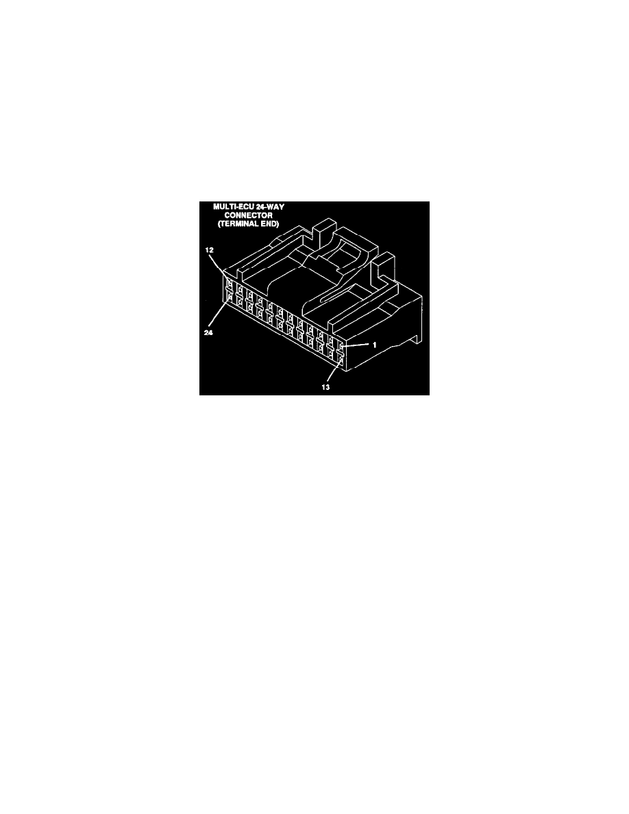
24 Way Connector
ECU CONNECTORS AND FUNCTIONS
CAV CIRCUIT
FUNCTION
1
YL
ECU fault code output, 12 volt pulses
2
DG/WT
SCI change terminal (grounded by DRBII adapter to change pin 1 to I/O port) Pin 1 then becomes SCI transmit & receive on
one wire
3
OPEN
4
WT
Oxygen sensor voltage 0-1 volt with digital voltmeter
5
DB/WT
12 volts to power steering switch, 0 volts with high steering pressure
6
OPEN
7
DG/RD
A/C switch sense, 12 volts when A/C is on
8
DB/YL
Intake air temperature sensor input
9
OPEN
10
WT/BK
5 volts out to air flow sensor
11
OPEN
12
WT/YL
5 volts out ignition timing adjust terminal ground to set timing
13
BK/DB
Fuel Pump check signal
14
YL/RD
12 volts to idle switch, grounded with closed throttle
15
LG/BK
California only, EGR temp. sensor input
16
PK
Barometric pressure sensor input, 4 volts key "ON" at sea level
17
BK
Sensor ground
18
YL/WT
5 volts out to speed sensor, 0 or 5 volts
19
DG/WT
TPS voltage input
20
YL/DG
Coolant sensor input
21
DB/WT
Crank angle sensor input
22
DB/RD
TDC sensor input
23
DG/VL
5 volt feed for ISC motor position sensor, TPS & barometric pressure sensor
24
BK
Sensor ground