
D50/Power Ram 50 V6-2972cc 3.0L SOHC (1990)
Acceleration/Deceleration Sensor: Testing and Inspection
Refer to SCHEMATIC DIAGRAMS/ELECTRICAL AND ELECTRONIC DIAGRAMS for wiring diagrams.
When the brake pedal is depressed, electric power and voltage are supplied to control unit through terminal No. 3. If there is an open in the circuit from
the stop light valve or stop light switch to control unit, the warning lamp comes on and the system is disconnected. This excludes vehicles with auto
cruise control system.
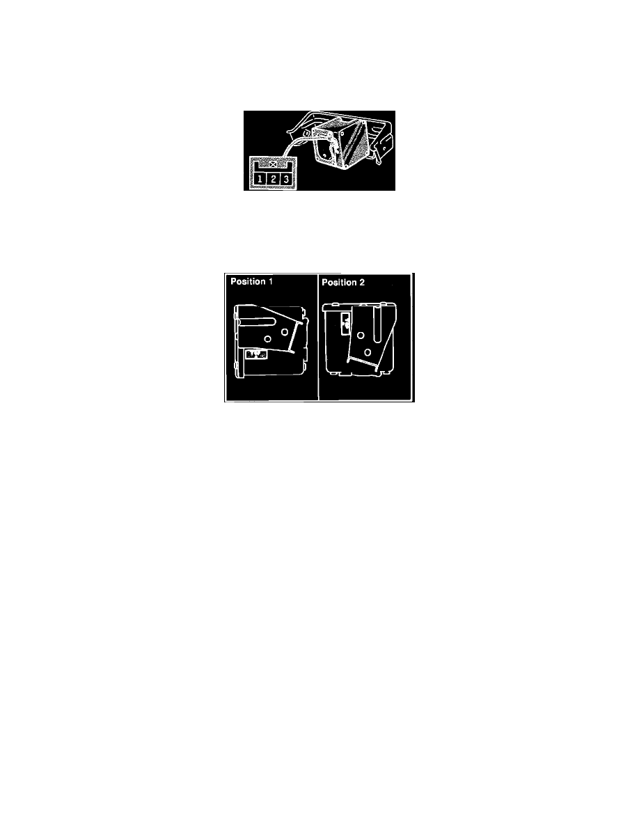
Fig. 6 G Sensor Terminal Identification
1.
Connect positive terminal to G sensor terminal 1 and negative terminal to terminal 3, then apply 7.3 volts.
2.
Connect voltmeter to terminal 2, then measure the variations of voltage when G sensor is operated.
3.
Standard value at position 1 should read 1.1--1.5 volts.
Fig. 7 Measuring G Sensor Voltage
4.
Standard value at position 2 should 4.6--5.0 volts.