
D50/Power Ram 50 V6-2972cc 3.0L SOHC (1990)
order to detect the two different slits. There is a very slight clearance between the luminous diodes and the photo diodes, and the disc rotates within this
space.
As the distributor shaft rotates the slits at the discs edge pass between the light and the optical reading part of the unit. The light emitted from the
luminous diodes pass through the slits to the photo sensing diodes. When the photo diodes receive the light, they become conductive and generate a
signal, which is sent to the Multi-Point Injection (MPI) Control Unit.
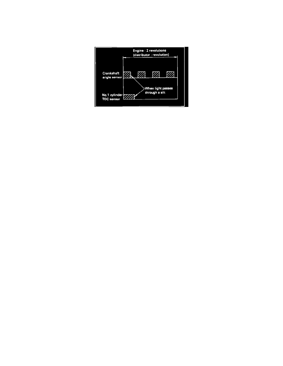
Photoelectric Signal Pattern
No.1 Cylinder TDC Signal:
Top dead center is detected by the signal obtained through the one inner slit of the disc. The MPI controller, based upon this signal, determines which of
the four pulses from crank angle sensor is the signal for the #1 cylinder.
Crankshaft Angle Signal:
The four slits located at the outer circumference of the disc serve to detect the position of the crankshaft (and, therefore, the piston) relative to top dead
center. The MPI controller, based on this signal, determines the fuel injection timing, and also calculates the amount of intake-air, the timing of the
ignition signal, etc. for each revolution of the engine.