
D50/Ram 50 L4-1997cc 2.0L SOHC (1984)
c. Install O-ring into side cover.
d. Align cross shaft with side cover and tighten with adjusting bolt, then tighten lock bolt temporarily.
e. Apply thin coat of multipurpose grease to lip of oil seal and press into top cover, then press fit ball bearing.
f.
Apply thin coat of ATF to O-ring and seal ring, then insert into seal housing. Install seal housing straight into gear box with O-ring side
positioned near mainshaft.
g. Apply thin coat of multipurpose grease to lip of oil seal, then press into gear box using tool No. CT-1008. Install back-up ring and snap ring.
Assembly
1. Apply thin coat of ATF to input worm unit O-rings and install O-rings and seal rings alternately onto worm unit. Do not apply excessive force.
2. Install thrust plate, thrust needle bearing and thrust plate to both ends of worm unit in that order, then apply thin coat of ATF to each.
3. Install O-ring and seal ring into groove of valve housing and apply thin coat of ATF to each.
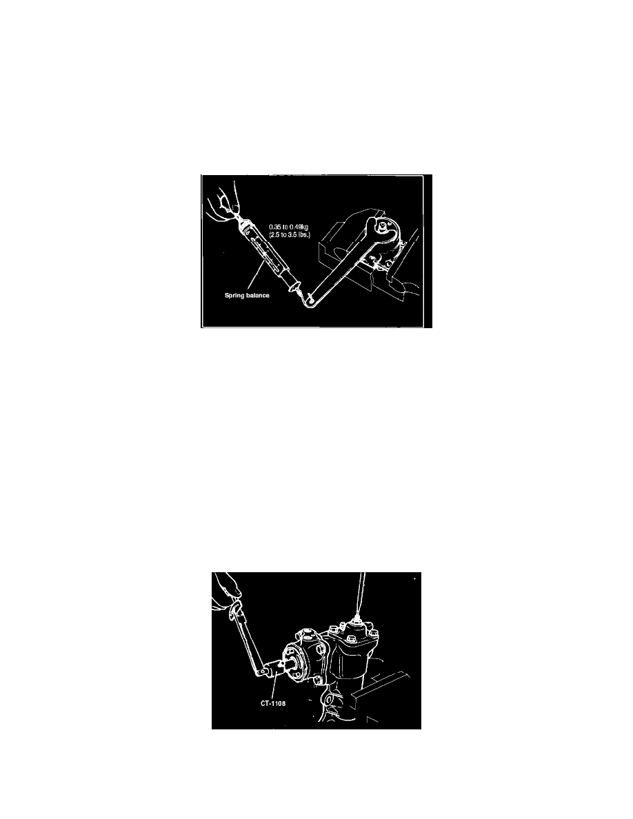
Fig. 8 Tightening of top cover
4. Install input worm unit into valve housing, then O-ring into top cover and top cover with bearing and oil seal onto valve housing. While turning
worm unit, tighten by using spring scale and special spanner wrench as shown. Rotate worm unit to check for uniform movement.
5. Install valve housing nut and tighten temporarily using tool No. MB990667 for large gear and No. MB990852 for small gear. Do not allow top
cover to rotate. The final tightening will occur during total starting torque measurement later in assembly procedure.
6. Measure starting torque by using tool No. CT-1108 and torque wrench while turning input worm unit, ensure preload is 3.5-6.9 in. lbs. If
necessary, readjust by loosening valve housing nut as in steps 4-5.
7. Install O-ring and seal ring to rack piston and apply thin coat of ATF to each.
8. Install rack piston into worm shaft until piston contacts worm shaft end, then insert 19 balls into groove through 2 openings on top of piston. Do
not rotate worm unit and piston while inserting balls. Do not allow hole to offset or turn during insertion of balls so balls will not fall into wrong
groove. After insertion of all balls, ensure balls reach approximately 0.080 inch for large gear, or 0.5 inch for small gear below end of piston.
Excessive clearance is an indication that a ball has fallen into wrong groove. If so, remove rack piston and insert balls.
9. Insert 7 balls into rack piston circulator. Apply multipurpose grease to balls to prevent them from falling from circulator. Install circulator and
holder into rack piston.
10. Secure gear box in vise, then install valve housing and rack piston assembly into gear box and torque bolts to 33-40 ft. lbs. After installation, rotate
assembly to move rack piston to neutral (center) position. Do not force rack piston into gearbox as seal ring may be damaged.
11. Apply thin coat of ATF to teeth and shaft of rack piston and multipurpose grease to oil seal lip of gear box, then install cross shaft assembly into
gearbox and torque side cover bolts to 33-40 ft. lbs.
Fig. 9 Measurement of total starting torque
12. Measure total starting torque of input worm shaft at neutral (center) position using tool No. CT-1108 and adjust to 3.6-7.1 in. lbs. for large gear or
4.3-7.8 in. lbs. for small gear by turning adjusting bolt. Torque valve housing nut to 130-166 ft. lbs. using tool No. MB990667 for large gear or