
D50/Ram 50 L4-2350cc 2.4L SOHC (1992)
Voltage Regulator: Testing and Inspection
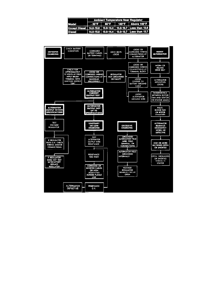
Fig. 4 Regulator Test Specification Chart
Fig. 5 Charging System Diagnosis Chart
1.
With ignition switch in the Off position, disconnect battery ground cable and connect a digital voltmeter between alternator S terminal and ground.
2.
Disconnect alternator output wire from alternator B terminal, then connect a DC ammeter in series between the B terminal and the disconnected
output wire. Connect positive lead of ammeter to B terminal. Connect negative lead to the disconnected output wire.
3.
Set engine tachometer and reconnect battery ground cable.
4.
Place ignition switch in the On position and note voltmeter. The reading should be equal battery voltage. If reading is 0, there is either an open
circuit in the wire between alternator S terminal and battery positive terminal or a blown fusible link.
5.
Start engine, keeping all accessories and lights off. Run engine at a constant 2500 RPM and read voltmeter when alternator output current drops to
10 amps or less. Note voltage readings, and refer to then refer to Charging System Diagnosis Chart.