
D50 2WD L4-156 2556cc 2.6L VIN 7 2-bbl (1982)
9. Separate upper ball joint from knuckle using tool No. C3894-A.
10. Remove bolts connecting upper arm shaft to arm post of side frame, then remove upper arm assembly.
11. Remove two bolts attaching lower arm then remove lower arm.
12. Reverse procedure to install, noting the following:
a. Refer to torque specifications.
b. Torque shock absorber lower mounting bolts to 6 to 8 ft. lbs. On 1984 models, tighten shock absorber upper mounting nut until protrusion of
stud above bottom of nut is 0.8 inch. On 1985-88 models, tighten shock absorber upper mounting nut until protrusion of stud above top of nut
is 0.5 inch for 1985 models or 0.27-0.31 inch for 1986 Ram 50 and 1987-88 Ram Raider. On 1987-88 Ram 50, tighten nut to end of threads.
On all models, install jam nut and torque to 9-13 ft. lbs.
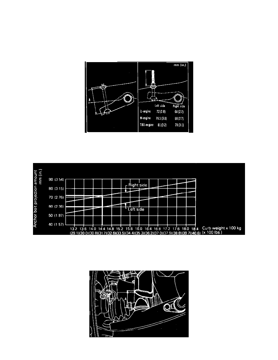
Fig. 2 Torsion bar anchor bolt installation. Ram 50 4 X 4, Ram Raider similar
c. Refer to image and check dimension A when torsion bar and anchor arm are assembled. Standard value is 5.6-5.8 inch for left side and
5.4-5.6 inch for right side on Ram 50, or 5.32-5.64 inches for left side and 4.9-5.2 inches for right side on Ram Raider.
Fig. 3 Torsion bar anchor bolt specifications. Ram Raider
d. Torque anchor bolt until protrusion is to specification shown for Ram 50 or for Ram Raider.
e. On 1984 models, tighten stabilizer bar to lower arm nut until protrusion of stud above bottom of nut is 0.63-0.71 inch. On 1985-88 models,
tighten stabilizer bar to lower arm nut until protrusion of stud above top of nut is 0.24-0.31 inch.
Fig. 4 Dimension between bump stop and bump stop bracket