
D 150 Ramcharger V8-360 5.9L (1989)
Turn Signal Switch: Service and Repair
Turn Signal/Hazard Warning Switch
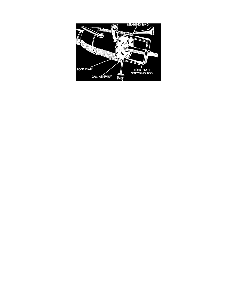
Lock plate retaining ring removal
1.
Disconnect battery ground cable.
2.
Remove lower bezel from instrument panel.
3.
Remove horn sounder and steering wheel. Refer to Steering and Suspension/Steering/Steering Wheel/Service and Repair.
4.
Remove wiring trough from underside of steering column by prying out retainer buttons.
5.
On standard columns, position gearshift to its full clock wise position. On tilt columns, position at mid-point.
6.
On all models, disconnect turn signal switch electrical connectors.
7.
On standard columns, proceed as follows:
a.
Remove upper bearing attaching screws, then the retainer.
b.
Remove screw holding wiper/washer switch to turn signal switch pivot. Leave turn signal lever in its installed position.
c.
Remove switch attaching screws from bearing housing, then the turn signal switch.
8.
On tilt columns, proceed as follows:
a.
Depress lock plate using tool C-4156 or equivalent then pry retaining ring out of groove. The full load of the upper bearing spring should
not be relieved. If full load is relieved, retaining ring will turn too easily, making removal more difficult.
b.
Remove lock plate, cancelling cam and upper bearing spring, then place turn signal lever in right turn position.
c.
Remove screw attaching link between turn signal switch and wiper/washer switch pivot. then the lever.
d.
Remove hazard warning switch knob attaching screw, then the turn signal switch attaching screws.
e.
Wrap a piece of tape around the connector and wire to prevent snagging during switch removal, remove turn signal/hazard warning switch
assembly by pulling switch up from column while straightening and guiding wires up through column opening.
9.
On all models, reverse procedure to install.