
D 250 Pickup V8-360 5.9L VIN W (1987)
If the valve is leaking, remove weight and stake the ball using a suitable drift punch. Exercise care when staking the ball to avoid damaging the bore
containing the pump weight. After staking with the old ball, remove and replace with new ball from tuneup kit. Install weight and re-check for leaks.
(4)
Install new gaskets on venturi cluster, then install cluster in position in main body (Fig. 13). Install cluster screws and tighten securely.
(5)
Install main metering jets (Fig. 11).
(6)
Install vacuum and mechanical power valves (2280 models only) using Special Tool C-4231 (Fig. 12). Be careful not to damage power valve
needles. CAUTION: Be sure the Power Valves are installed in their proper location, Mechanical Valve on choke side and Vacuum Valve on
Throttle Lever Side.
(7)
A nitrophyl float can be checked for fuel absorption by lightly squeezing between fingers. If wetness appears on surface or float feels heavy
(check with known good float), replace the float assembly.
(8)
Install hinge pin in float assembly. Insert hinge through slot in float baffle with tabs on baffle pointing downward. Position assembly in hinge
pin cradle in carburetor main body (Fig. 10).
(9)
Place a new gasket on fuel inlet fitting and install assembly into main body, tighten securely to 180 inch pounds (20 N-m). Check float level.
Refer to carburetor adjustments for adjusting procedure.
(10)
Install feedback solenoid on 6280 models.
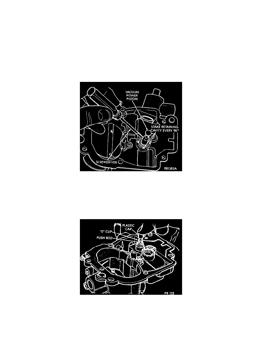
FIGURE 17 - SERVICING VACUUM POWER VALVE PISTON AND RETAINING RING
Air Horn
(1)
Test freeness of choke mechanism in air horn. The choke shaft must float free to operate correctly. If choke sticks in bearing bores, or appears to
be gummed from deposits in air horn, a thorough cleaning will be required.
(2)
Before installing the vacuum power valve assembly in bowl cover, be sure and remove all staking from the retainer cavity. Install the spring and
piston in the vacuum cylinder, seat the retainer and stake lightly with suitable tool (Fig. 17). Compress piston to be sure no binding exists. If piston
sticks or binds enough to hinder smooth operation, a new piston should be installed.
FIGURE 18 - SERVICING MECHANICAL POWER VALVE PUSH ROD
(3)
Install mechanical power valve push rod spring, push rod and "E" clip retainer. Push plastic cap on to push rod (2280 models only) (Fig. 18).
(4)
Install accelerator pump plunger assembly through air horn and attach internal lever with C-link (2280 models only). On 6280 models, install new
accelerator pump cup.
(5)
Place a new gasket on air horn. Lower air horn straight down on main body; guiding accelerator pump plunger into its cylinder. Do not cut lip of