
D 350 Pickup V8-360 5.9L VIN 5 (1992)
17.
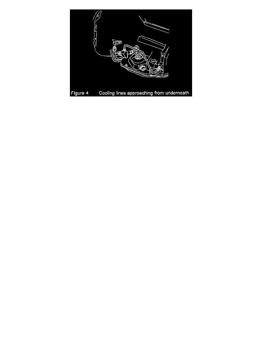
Using figures 2, 3, 4, select the appropriate "RR" and "P" tubes for the application.
18.
Loosely connect the pressure line "P" to the pressure port fitting "P" on the bypass assembly block.
19.
Loosely connect the radiator return line, "RR" to the "RR" port fitting, on the bypass assembly block.
NOTE:
During the installation of the "p" and "rr" lines, the order may be reversed to aid in the assembly process.
20.
Make sure that the existing return line is properly re-attached to the hanger bracket and lay the new return line, "RR" beside it
21.
Install the hose bracket (12) (required for the overhead line application). Figure 2
NOTE:
When attaching the compression sleeve, refer to figure 2 for proper orientation of the sleeve.
22.
Attach clamp (11) and the rubber hose to the "RR" tube and determine the approximate rubber hose routing. For connection to the existing return
line, the existing return line may be cut again to provide optimum line routing.
CAUTION:
When routing the tubing and hose be aware of potential moving component interferences, such as the propeller shaft, shift linkage in all
positions, TV cable, TV return spring, and TV linkage. Be aware of the exhaust system, all routings should maintain at least one inch of
clearance from the exhaust system.
23.
Cut the rubber hose so that it has sufficient length to be attached to the existing return line.
24.
Loosely connect a nut (7), a compression sleeve (8), and a hose fitting (10) to the existing return line.
25.
Using a clamp (11), install the rubber hose onto the hose fitting (10).
26.
Evaluate the line routing to ensure moving components and exhaust will not interfere with the new lines.
27.
Disconnect the "RR" tube (3) from the By-Pass Block for access to the "P"; port on the block assembly.
NOTE:
When attaching the compression sleeve, refer to figure 2 for proper orientation of the sleeve.
28.
Attach a clamp and the rubber hose to the "P" tube and determine the approximate rubber hose routing. For connection to the existing pressure
line, the existing pressure line may be cut again to provide optimum line routing.
CAUTION:
When routing the tubing and hose be aware of potential moving component interferences, such as the propeller shaft, shift linkage in all
positions, TV cable, TV return spring, and TV linkage. Be aware of the exhaust system, all routings should maintain at least one inch of
clearance from the exhaust system.
29.
Cut the rubber hose so that it has sufficient length to be attached to the existing pressure line.
30.
Loosely connect a nut (7), a compression sleeve (8), and a hose fitting (10) to the existing pressure line.
31.
Using a clamp (11), install the rubber hose onto the hose fitting (10).
32.
Evaluate the line routing to ensure moving components and exhaust will not interfere with the new lines.
33.
Torque both clamps, the compression fitting (finger tight, then wrench tighten 1/2 turn), and the inverted flare nut to 60 in lbs on the "P" line.
34.
Connect the "RR" tube and torque both clamps, the compression fitting (finger tight, then wrench tighten 1/2 turn), and the inverted flare nut to 60
in lbs on the "P" line.
35.
Re-check to ensure that all connections have been securely tightened.
36.
Refer to Figure 2 for view of completed assembly.