
Dakota 2WD L4-2.5L VIN P (2001)
Remove the bearing cap. Determine the amount of clearance by measuring the width of the compressed Plastigage with the scale on the Plastigage
envelope (Fig. 40). Refer to Engine Specifications for the proper clearance.
Plastigage should indicate the same clearance across the entire width of the insert. If clearance varies, it may indicate a tapered journal or foreign
material trapped behind the insert.
If the specified clearance is indicated and there are no abnormal wear patterns, replacement of the bearing inserts is not necessary. Remove the
Plastigage from the crankshaft journal and bearing insert. Install bearings.
If the clearance exceeds specification, install a pair of 0.025 mm (0.001 inch) undersized bearing inserts and measure the clearance as described in the
previous steps.
The clearance indicated with the 0.025 mm (0.001 inch) undersized insert pair installed will determine if this insert size or some other combination
will provide the specified clearance. FOR EXAMPLE: If the clearance was 0.0762 mm (0.003 inch) originally, a pair of 0.0254 mm (0.001 inch)
undersized inserts would reduce the clearance by 0.0254 mm (0,001 inch). The clearance would then be 0.0508 mm (0.002 inch) and within the
specification. A 0.051 mm (0,002 inch) undersized bearing insert and a 0.0254 mm (0.001 inch) undersized insert would reduce the original
clearance an additional 0.0127 mm (0.0005 inch). The clearance would then be 0.0381 mm (0.0015 inch).
CAUTION: Never use a pair of inserts that differ more than one bearing size as a pair.
FOR EXAMPLE: DO NOT use a standard size upper insert and a 0.051 mm (0.002 inch) undersized lower insert.
If the clearance exceeds specification using a pair of 0.051 mm (0.002 inch) undersized bearing inserts, measure crankshaft journal diameter with a
micrometer. If the journal diameter is correct, the crankshaft bore in the cylinder block may be misaligned, which requires cylinder block replacement
or machining to true bore.
If journals 1 through 5 diameters are less than 63.4517 mm (2.4981 inches), replace crankshaft or grind crankshaft down to accept the appropriate
undersized bearing inserts.
Once the proper clearances have been obtained.
Crankshaft Main Bearing Inspection
INSPECTION
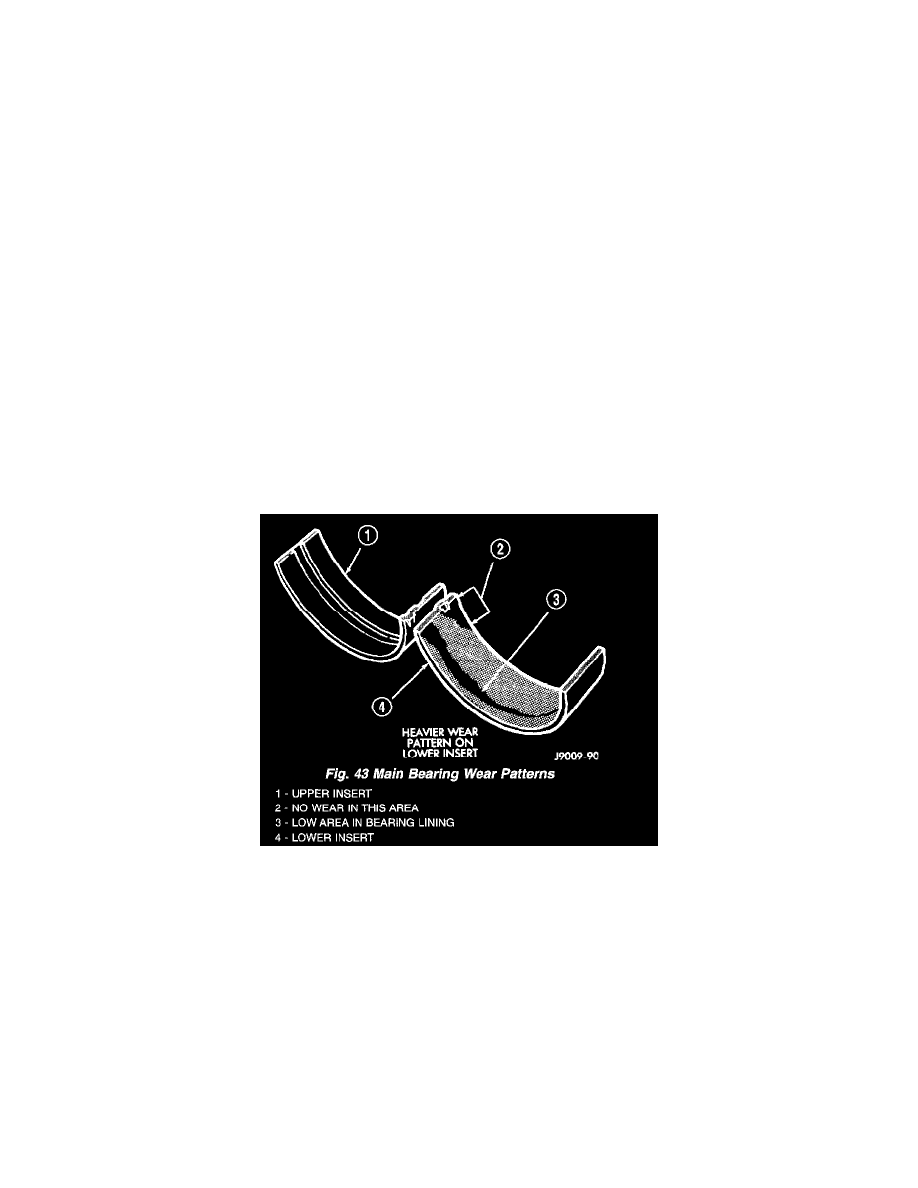
Wipe the inserts clean and inspect for abnormal wear patterns and for metal or other foreign material imbedded in the lining. Normal main bearing
insert wear patterns are illustrated (Fig. 43).
NOTE: If any of the crankshaft journals are scored, remove the engine for crankshaft repair.
Inspect the back of the inserts for fractures, scrapings or irregular wear patterns.
Inspect the upper insert locking tabs for damage.
Replace all damaged or worn bearing inserts.