
Dakota 2WD L4-2.5L VIN P (2001)
Turn Signal Flasher: Description and Operation
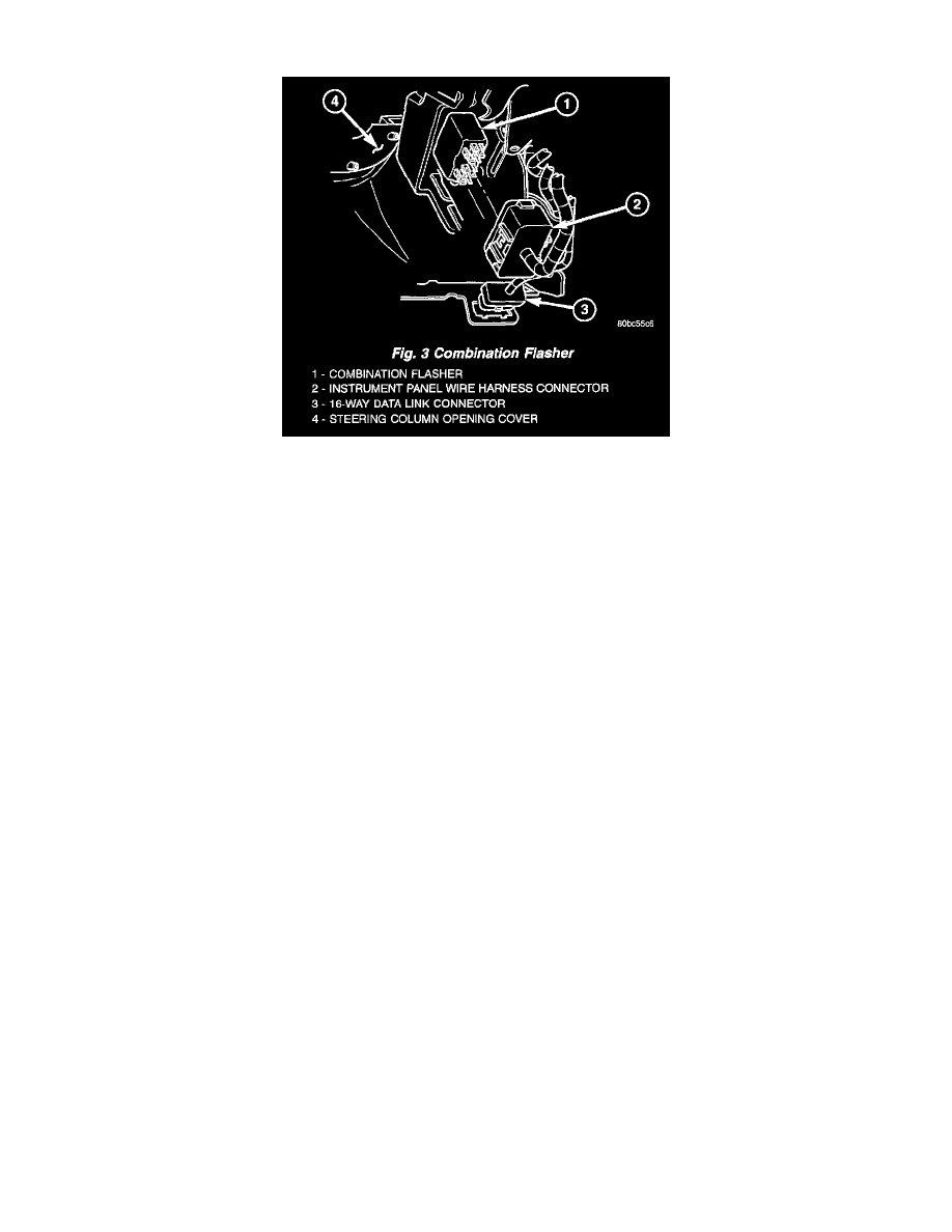
Fig.3 Combination Flasher
COMBINATION FLASHER
The combination flasher is located in a dedicated connector on a take out of the instrument panel wire harness, located under the instrument panel
just outboard of the instrument panel steering column opening. The combination flasher is a smart relay that functions as both the turn signal
system and the hazard warning system flasher. The combination flasher has fourteen blade-type terminals that connect it to the vehicle electrical
system through fourteen matching cavities in the instrument panel wire harness connector; however, only ten of the combination flasher terminals
are used in this application. The combination flasher contains active electronic Integrated Circuitry (IC) elements. This flasher is designed to
handle the current flow requirements of the factory-installed lighting. If supplemental lighting is added to the turn signal lamp circuits, such as
when towing a trailer with lights, the combination flasher will automatically try to compensate to keep the flash rate the same.
The combination flasher cannot be repaired or adjusted and, if faulty or damaged, it must be replaced.
The combination flasher has fourteen blade-type terminals, but only ten are used in this application. These ten terminals are intended for the
following inputs and outputs: fused B(+), fused ignition switch output, right turn signal sense, left turn signal sense, hazard flasher signal, brake
lamp switch output, and two outputs each for the right and left turn signal circuits. Constant battery voltage is supplied to the flasher so that it can
perform the hazard warning function, and ignition switched battery voltage is supplied for the turn signal function. The Integrated Circuit (IC)
within the combination flasher contains the logic that controls the flasher operation and the flash rate. The IC receives separate sense ground inputs
from the multi-function switch for the hazard flasher, right turn signal, and left turn signal. A special design feature of the combination flasher
allows it to "sense" that a turn signal circuit or bulb is not operating, and provide the driver an indication of the condition by flashing the remaining
bulbs in the affected circuit at a higher rate (120 flashes-per-minute or higher). Conventional flashers either continue flashing at their typical rate
(heavy-duty type), or discontinue flashing the affected circuit entirely (standard-duty type).
Because of the active electronic elements within the combination flasher, it cannot be tested with conventional automotive electrical test
equipment. If the combination flasher is believed to be faulty, test the turn signal and hazard warning system. Then replace the combination flasher
with a known good unit to confirm system operation. (Refer to TURN SIGNAL & HAZARD WARNING SYSTEM - DIAGNOSIS AND
TESTING).