
Dakota 2WD L4-2.5L VIN P (2001)
13.
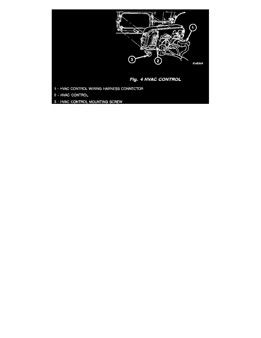
Remove the four screws that secure the HVAC control to the cluster bezel (Fig. 4).
14.
Remove the HVAC control from the instrument panel.
15.
Position the new HVAC control (see Parts Required section) in the cluster bezel and secure it with four screws. Tighten the screws to 2.2 Nm (17
i3 in. lbs.)
16.
Position the cluster bezel to the instrument panel.
17.
Pull the left side of the cluster bezel away from the instrument panel far enough to access and reconnect the instrument panel wire harness
connectors to the receptacles for the passenger airbag on/off switch (if equipped), the rear window defogger switch (if equipped), the HVAC
control, and the transfer case switch (if equipped).
18.
Pull the right side of the cluster bezel away from the instrument panel far enough to access and reconnect the instrument panel wire harness
connector for the headlamp switch to the switch connector receptacle.
19.
Align the snap clips on the cluster bezel with the receptacles in the instrument panel base trim.
20.
Using hand pressure, press firmly on the cluster bezel over each of the snap clip locations until each snap clip is fully engaged in their receptacle.
21.
Install and tighten the two screws in the hooded area above the instrument cluster that secure the cluster bezel to the instrument panel base trim
(Fig. 3). Tighten the screws to 2.2 Nm (20 in. lbs.).
22.
Position the steering column opening cover to the instrument panel.
23.
Align the snap clip retainers on the steering column opening cover with the receptacles in the instrument panel base trim.
24.
Using hand pressure, press firmly on the steering column opening cover over the snap clip locations until each of the snap clips are fully engaged
in their receptacle.
25.
Install and tighten the three screws that secure the lower edge of the steering column opening cover to the instrument structural support. Tighten
the screws to 2.2 Nm (20 in.lbs.).
26.
Reach under the left end of the instrument panel to access and engage the park brake release link to the back of the handle. Then snap the rod end
clip over the park brake release link to secure the connection.
27.
Reconnect the battery negative cable.
28.
On vehicles equipped with A/C, perform the A/C cool down test using the DRBIII(R).