
Dakota 2WD V6-239 3.9L (1987)
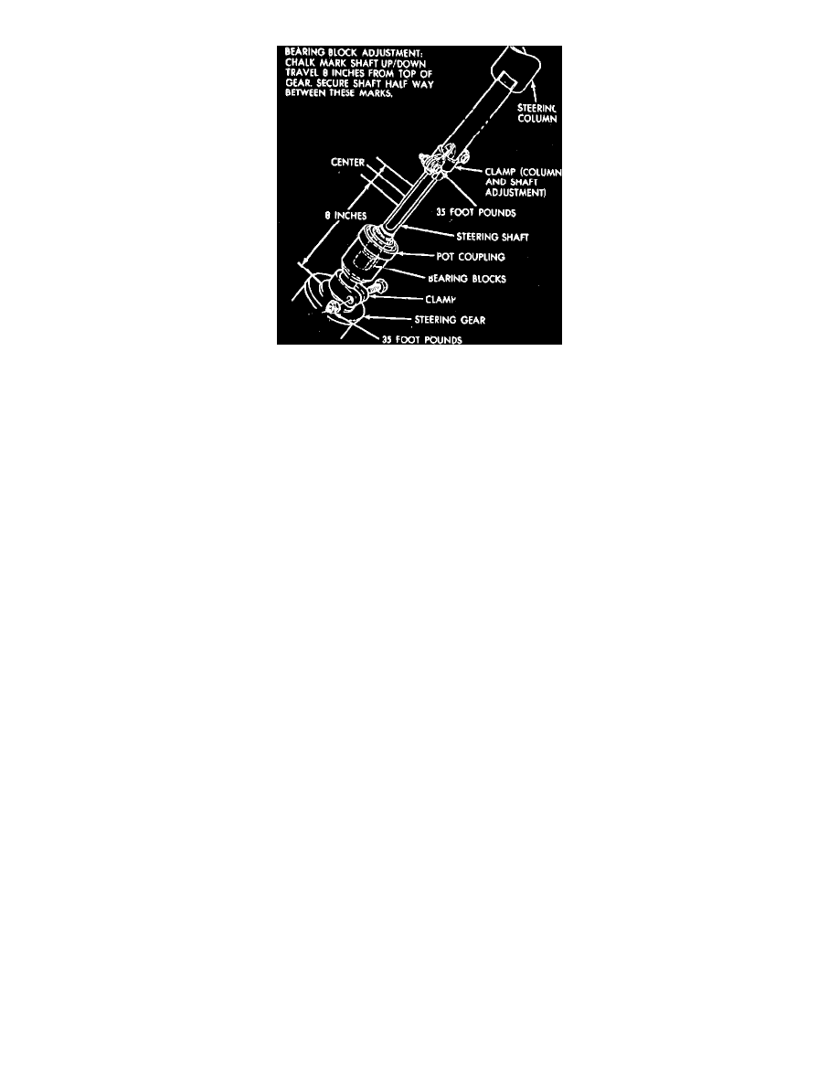
Fig. 2 Steering column coupling & shaft adjustment. Motor Home
Tilt Column Release Pedal Adjustment
1. Loosen pedal assembly locknut at adjustable mounting bracket assembly.
2. Move column adjusting assembly foot pad rearward, toward the driver, 0.040 inch from center line of rear column adjustable mounting bracket
bolt. While holding pedal in this position, tighten nut until column is locked securely.
3. Test operation of column adjusting pedal by depressing and releasing several times. If correctly adjusted, the pedal will return to the approximate
position shown.
DAKOTA
Removal
1. Disconnect battery ground cable.
2. On models with column shift, disconnect link rod by prying rod from grommet in shift lever.
3. On all models, remove steering shaft lower coupling to worm shaft roll pin, then disconnect wiring connectors at steering column jacket.
4. Remove steering wheel center pad assembly, then disconnect horn wires.
5. Remove horn switch, if equipped, then the steering wheel retaining nut.
6. Using tool No. C-428B, remove steering wheel assembly.
7. Remove floor plate to floor pan attaching screws.
8. Remove instrument panel steering column cover, then the lower reinforcement.
9. Remove steering column bracket to instrument panel support attaching nuts, then lower coupling from steering gear worm shaft.
10. Remove column assembly through passenger compartment, using care not to damage surrounding components.
11. Remove four lock housing to column jacket retaining screws, then the lock housing plate and housing from jacket.
12. Rotate lock housing 90 degrees to disengage from ignition switch and actuator rod, then remove.
Installation
1. Install ground clip on left capsule slot, then insert column through floor pan opening, using care not to damage surrounding components.
2. Place front wheel in a straight ahead position with master splines on worm shaft and coupling aligned, then engage coupling with worm shaft and
install roll pin.
3. Hold column assembly with bracket slots on mounting studs, then install, but do not tighten, upper bracket, washers and nuts.
4. Ensure both breakaway capsules are fully seated in support bracket slots, then torque two upper bracket attaching nuts to 110 inch lbs.
5. Position floor plate over floor pan opening, then install and securely tighten retaining bolts.
6. Place steering wheel on steering shaft, then install retaining nut and torque to 45 ft. lbs.
7. Connect wiring connectors at steering column jacket, then temporarily connect battery ground cable and test horn and light operations.
8. Connect link rod to shift lever by snapping rod into new grommet, using a suitable tool.
9. Adjust linkage, then connect gearshift indicator pointer in its original position. Move lever from "L" to "P" pausing briefly at each position and
ensuring pointer is properly aligned.
10. Install lower reinforcement, then the instrument panel steering column cover.
11. Connect battery ground cable.
Disassembly/Assembly