
Dakota 2WD V6-239 3.9L (1987)
Ball Joint: Service and Repair
Upper Ball Joint Replacement
2 WHEEL DRIVE MODELS
Upper Ball Joint
1. Place ignition switch in the "Off" position.
2. Using a suitable jack raise front of vehicle and position a jack stand under lower control arm as close to wheel and tire assembly as
possible.
3. Remove wheel and tire assembly.
4. Remove cotter pin and nut from upper ball joint nuts.
5. Using tool No. C3564-A or equivalent, free upper ball joint from knuckle.
6. Using tool No. C3561 or equivalent, unscrew ball joint from control arm. Support knuckle and brake assembly to prevent damage to
lower ball joint and brake hoses.
7. Reverse procedure to install. Thread upper ball joint into control arm as far as possible by hand. Torque upper ball joint into control arm to 125 ft.
lbs. Install ball joint seal using suitable 2 inch socket. Install ball joint into steering knuckle, then torque attaching bolts to 135 ft. lbs.
Lower Ball Joint
1. Raise and support vehicle, then remove wheel and tire assembly.
2. Remove brake caliper assembly and support aside with suitable rope or wire. Do not allow brake caliper to hang by hydraulic hose.
3. Remove shock absorber. Insert spring compressor tool DD-1278 and a piece of pipe to take up excessive space between tool and control arm.
Tighten finger tight, then back off 1/2 turn.
4. Remove cotter pin and nut from lower ball joint.
5. Using tool No. C3564-A or equivalent, free lower ball joint from knuckle.
6. Remove ball joint seal.
7. Press ball joint from lower control arm with tool C-4212.
8. Reverse procedure to install. Torque lower ball joint attaching nut to 135 ft. lbs.
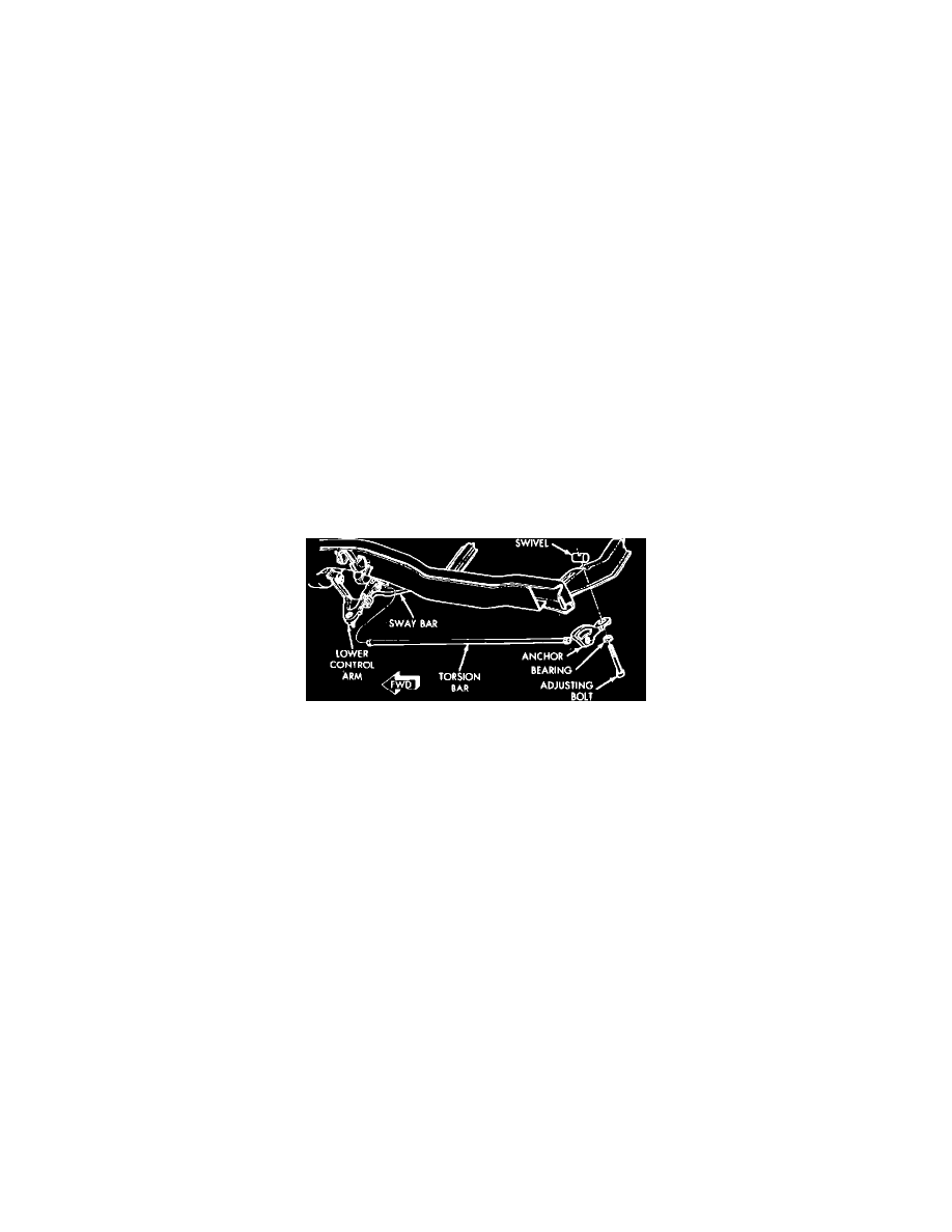
Fig. 2 Lower control arm and torsion spring. 4 wheel drive models
4 WHEEL DRIVE MODELS
Upper Ball Joint
1. Remove cotter pin, locknut and spring washer from wheel hub.
2. While applying brakes, loosen hub nut.
3. Raise and support vehicle with front suspension in full rebound.
4. Remove hub nut and washer, then wheel and tire assembly.
5. Remove driveshaft to axle flange attaching bolts, then remove driveshafts.
6. Loosen rear torsion bar anchor adjusting bolt to unload suspension.
7. Remove cotter pin and nut from upper ball joint.
8. Position ball joint removal tool C-3564-A on upper ball joint, then tighten tool and strike upper control arm with suitable hammer to remove ball
joint.
9. Reverse procedure to install, noting the following:
a. Press new ball joint into control arm with tool No. C-4212, then install new seal.
b. Torque ball joint to steering knuckle attaching nut to 135 ft. lbs.
c. Torque driveshaft to axle flange attaching bolts to 65 ft. lbs.
d. Torque hub nut to 180 ft. lbs.
e. Adjust torsion bars to set ride height. Refer to "Front Suspension Height, Adjust" for procedure.
Lower Ball Joint
1. Remove cotter pin, locknut and spring washer from wheel hub.
2. While applying brakes, loosen hub nut.
3. Raise and support vehicle with front suspension in full rebound.
4. Remove hub nut and washer, then wheel and tire assembly.
5. Remove driveshaft to axle flange attaching bolts, then remove driveshafts.