
Dakota 2WD V6-239 3.9L Magnum (1996)
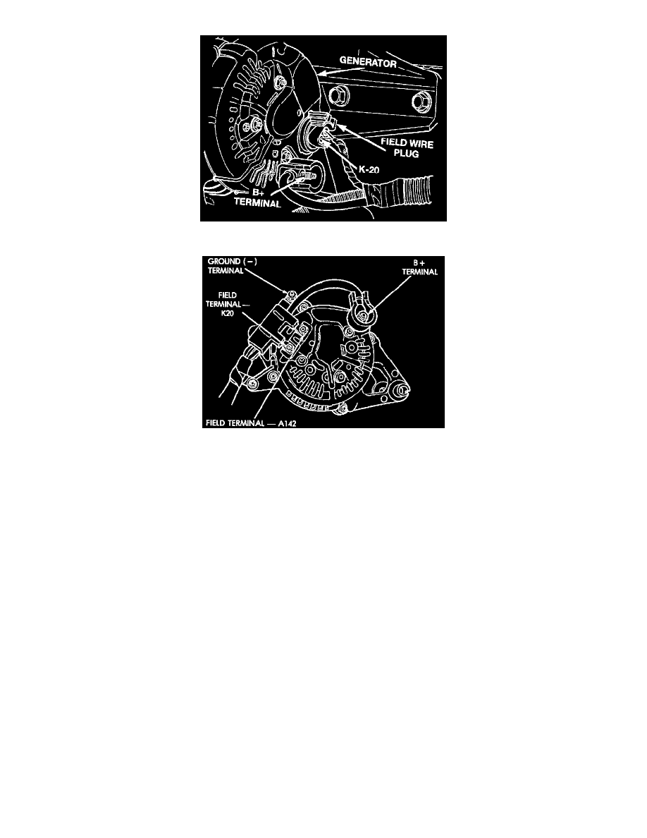
Fig. 4 Alternator Connections (Plug Type)
Fig. 5 Alternator Connections (Nut Type)
6. Connect suitable jumper wire to ground and K20 (field driver) terminal at rear of alternator. This may generate a fault code. Do not connect
powered field circuit to ground, as component damage will occur.
7. Connect a suitable engine tachometer, then reconnect battery ground cable.
8. Ensure carbon pile is in OPEN or OFF position, then connect a variable carbon pile rheostat to battery terminals.
9. Start engine and operate at idle speed, then adjust carbon pile and engine speed to maintain a 20 amp circuit flow. Note voltmeter reading.
Voltmeter reading should not exceed 0.5 volt.
TEST RESULTS
1. If a higher than specified voltage drop is indicated, clean and tighten all connectors in charging circuit. A voltage drop inspection may be
performed at each connector to locate point of excessive resistance.
2. If charging circuit resistance inspection was satisfactory, disconnect battery ground cable, then the ammeter, voltmeter, carbon pile and
tachometer.
3. Remove jumper wire.
4. Connect battery ground cable, then the hose between Engine Controller and air cleaner.
5. Erase codes using DRB inspection tool or equivalent scan tool.
Output Current Test
TEST PROCEDURE
1. Disconnect battery ground cable.
2. Disconnect "B+" lead at alternator output terminal.