
Dakota 2WD V6-3.9L VIN X (1997)
Electronic Brake Control Module: Description and Operation
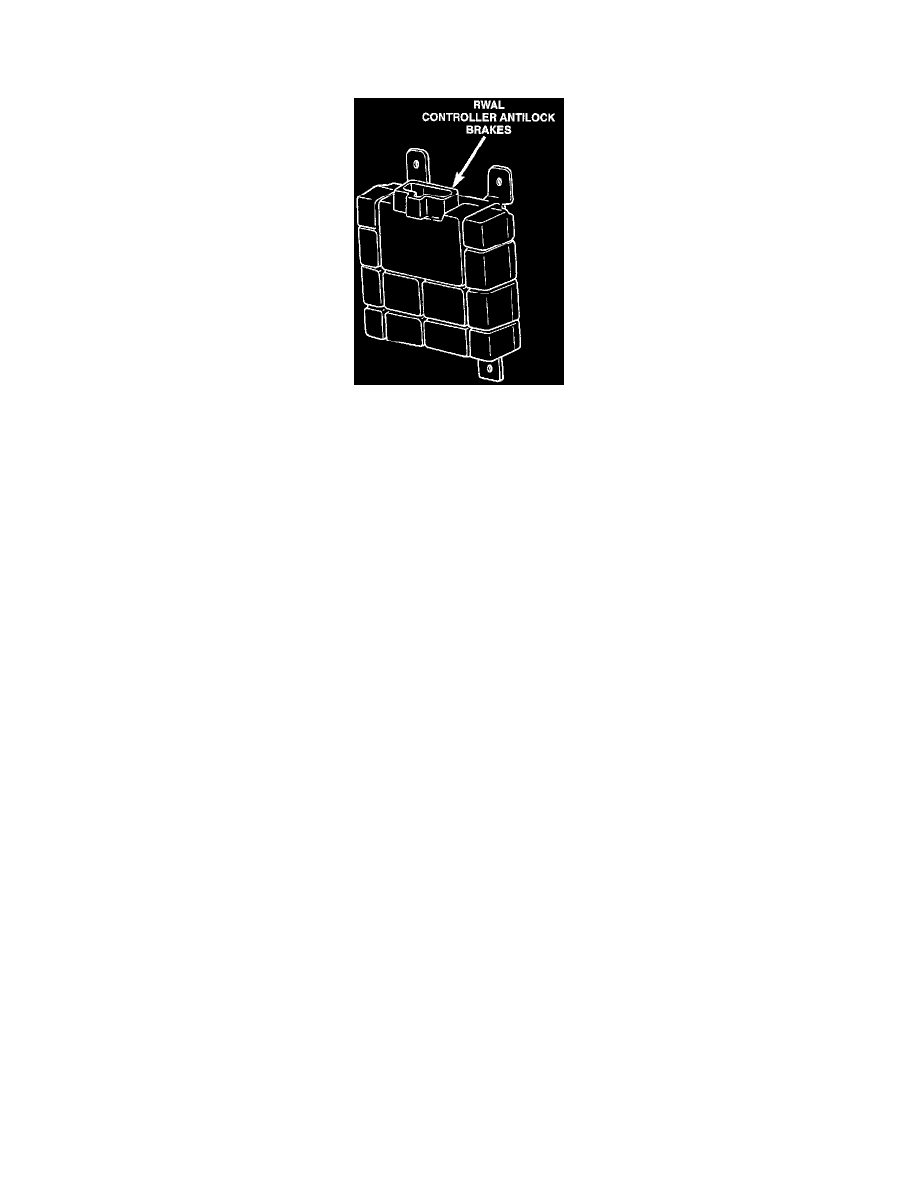
With Rear Wheel Antilock Brakes
GENERAL INFORMATION
The Controller Anti-Lock Brake (CAB) is a microprocessor which monitors and controls the Anti-Lock Brake System (ABS) operation. It has a
14 terminal connector to deliver power and ground and to connect all inputs and outputs associated with the system. The CAB primary functions
are:
^
Detect wheel locking tendencies.
^
Control the application of brake fluid pressure to the rear brakes during ABS braking.
^
Monitor the Rear Wheel Anti-Lock (RWAL) brake system for proper operation.
^
Perform self-check diagnostics.
The CAB continuously monitors the speed of the differential ring gear by monitoring signals generated by the rear wheel speed sensor. The CAB
determines a wheel locking tendency when it recognizes the ring gear decelerating too rapidly.
When a wheel-locking tendency is detected, the CAB energizes the isolation solenoid in the RWAL valve. When the isolation solenoid is
energized, hydraulic pressure cannot be increased to the rear wheel cylinders. If the rear wheel speed sensor still indicate that the ring gear is
decelerating too rapidly, the CAB then energizes the dump solenoid to reduce pressure at the rear wheel cylinders. The CAB continues this action
until the wheel-locking tendency no longer exists.
ON-BOARD DIAGNOSTICS
When a fault is detected, the CAB will generate and store diagnostic trouble codes. Only one code can be stored at any one time. If the CAB
senses a fault in any one of its monitored circuits, it will illuminate the red brake warning and ABS warning lamps. It will then generate a
Diagnostic Trouble Code (DTC) and store it in memory. In general, the diagnostic trouble code will remain in memory when the ignition key has
been turned Off. The exception to this is Diagnostic Trouble Codes 9 and 11, which are erased any time the key has been turned to the Off
position. Also, Diagnostic Trouble Code 11 will be removed from memory when the ignition switch is in the Run or Accessory positions if the
malfunction has been eliminated. If the malfunction remains, Diagnostic Trouble Codes 9 and 11 will be reset on the next ignition key cycle to On.
INPUTS
The CAB monitors the following inputs to determine when a wheel locking tendency may exist:
^
Rear Wheel Speed Sensor
^
Brake Lamp Switch
^
Brake Warning Lamp Switch
^
Reset Switch
^
4WD Switch (If equipped)
OUTPUTS
The CAB controls the following outputs for anti-lock braking and brake warning information:
^
RWAL Valve
^
ABS Warning Lamp
^
Brake Warning Lamp
POWER SUPPLY & GROUND
Ignition voltage is provided to the CAB through connector pin 3 and is protected by a 20 amp fuse. Ignition voltage is supplied when the ignition
switch is in the Run or Accessory positions. The CAB requires ignition voltage to be able to operate the anti-lock brakes. Battery voltage is
provided to the CAB through pin 9 and is protected by a 20 amp fuse. This circuit supplies power to the memory cells so that the CAB can retain
diagnostic information. Except for Diagnostic Trouble Codes 9 and 11, the CAB stores DTCs in the battery fed volatile memory. Volatile
memories only retain information as long as power is supplied to the memory. If a DTC is stored in the battery fed volatile memory, the DTC can