
Dakota 2WD V8-4.7L VIN J (2005)
Memory Positioning Module: Description and Operation
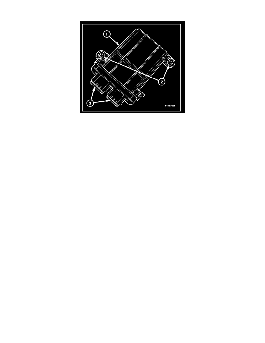
The Occupant Classification Module (OCM) (1) is secured with two screws to a stamped metal mount on the underside of the passenger side front seat
cushion frame near the center. Concealed within a hollow in the center of the molded plastic OCM housing is a microprocessor and the other electronic
circuitry of the module. The module housing is sealed to enclose and protect the internal electronic circuitry. The OCM software is flash programmable.
Two mounting tabs (2) and two connector receptacles (3) are integral to the OCM housing. The connector receptacles contain terminal pins that connect
the OCM to the vehicle electrical system through a dedicated take out and connector of the passenger side front seat wire harness, and a second take out
and connector of the body wire harness.
A non-calibrated OCM is available for separate service replacement. The OCM and all of the other components of the Occupant Classification System
(OCS) including the passenger side front seat, the seat weight sensors, the passenger or driver seat track position sensor and the seat adjusters, cushion,
back, frame, foam, springs, and wiring harness are a factory-calibrated and assembled unit. Any time any one of these components is removed or
replaced for any reason, the OCM must be re-calibrated using a diagnostic scan tool, the Occupant Classification Seat Weight special tool, and the
Occupant Classification System Verification Test.
The OCM cannot be adjusted or repaired and, if damaged or faulty, it must be replaced.
The microprocessor in the Occupant Classification Module (OCM) contains the Occupant Classification System (OCS) logic circuits. The OCM uses
On-Board Diagnostics (OBD) and can communicate with other electronic modules in the vehicle as well as with the diagnostic scan tool using the
Controller Area Network (CAN) data bus. This method of communication is also used for OCS diagnosis and testing through the 16-way data link
connector located on the driver side lower edge of the instrument panel.
The OCM provides voltage to the four seat weight sensors located on the corners of the passenger side front seat, and to the seat track position sensors
on the outboard passenger and driver side front seat upper seat tracks. The OCM then monitors return inputs from each of the sensors on dedicated hard
wired data communication circuits. The seat weight sensor input allows the OCM to determine whether the passenger side front seat is occupied and the
relative size of the occupant by providing a weight-sensing reference to the load on the seat. The seat track position sensor provides an additional logic
input to the OCM microprocessor that allows it to determine the position of the front seat passenger and driver relative to the front airbags.
Pre-programmed decision algorithms and OCS calibration allow the OCM microprocessor to determine when passenger airbag protection is appropriate
based upon the seat load as signaled by the seat weight sensors. When the programmed conditions are met, the OCM sends the proper electronic
occupant classification messages over the CAN data bus to the Occupant Restraint Controller (ORC), and the ORC enables or disables the deployment
circuits for the passenger front supplemental restraints. The ORC also provides a control output for the passenger airbag on/off indicator in the
instrument panel based upon the electronic occupant classification messages it receives from the OCM.
The OCM also sends electronic driver and passenger seat track position messages to the ORC over the CAN data bus. The ORC uses the seat track
position data as an additional logic input for determining the force level with which to deploy the multistage front airbags.
The OCM microprocessor continuously monitors all of the OCS electrical circuits and components to determine the system readiness. If the OCM
detects a monitored system fault, it sets an active and stored Diagnostic Trouble Code (DTC) and sends the appropriate electronic messages to the ORC
over the CAN data bus. Then the ORC sets a DTC and sends messages to control the airbag indicator operation accordingly. An active fault only remains
for the duration of the fault, or in some cases for the duration of the current ignition switch cycle, while a stored fault causes a DTC to be stored in
memory by the OCM and the ORC. For some DTCs, if a fault does not recur for a number of ignition cycles, the OCM will automatically erase the
stored DTC. For other internal faults, the stored DTC is latched forever.