
Dakota 2WD V8-4.7L VIN J (2005)
Seat Heater Control Module: Testing and Inspection
NOTE: Before testing the individual components in the heated seat system, check the vehicles battery open-circuit voltage and charging system
performance. If the vehicles electrical system is defective or weak it may not be suppling sufficient energy to operate the heated seat system.
If a heated seat fails to heat and one or both of the indicator lamps on a heated seat switch flash, Refer to testing for flashing LED diagnosis and testing
procedures. The wiring information includes wiring diagrams, proper wire and connector repair procedures, details of wire harness routing and retention,
connector pin-out information and location views for the various wire harness connectors, splices and grounds.
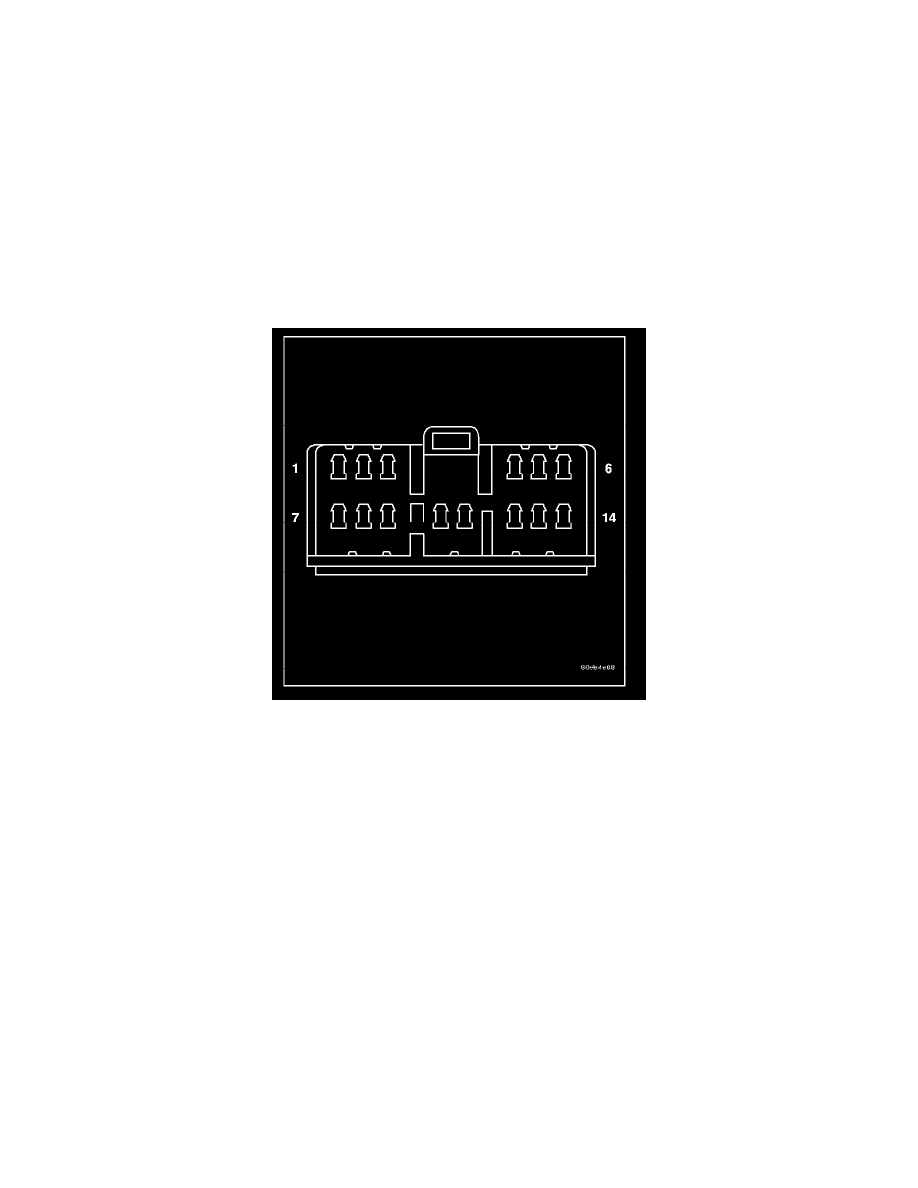
1. Remove the heated seat module from its mounting location.
NOTE: ANY RESISTANCE VALUES (OHMS V) GIVEN IN THE FOLLOWING TEXT ARE SUPPLIED USING THE AUTOMATIC
RANGE GENERATED BY A FLUKE(R) AUTOMOTIVE METER. IF ANOTHER TYPE OF MEASURING DEVICE IS USED THE
VALUES GENERATED MAY NOT BE THE SAME AS THE RESULTS SHOWN HERE, OR MAY HAVE TO BE CONVERTED TO THE
RANGE USED HERE.
RIGHT SEAT HEATER INOPERATIVE
1. If a heated seat heats but one or both indicator lamps (LED's) on the heated seat switch fail to illuminate, check the driver circuit with the
inoperative LED for a short to ground. If OK, replace the heated seat switch. If NOT OK repair the short to ground as required and than replace
the heated seat switch.
NOTE: IF THE RIGHT SEAT CUSHION IS ALREADY WARM THE FOLLOWING STEP WILL NOT PROVE CONCLUSIVE.
2. Back-probe the heated seat module wire harness connector, do not disconnect. Check cavity #3 for battery voltage when the right heated seat
switch is turned "ON", voltage should be present, If OK go to Step 3 If NOT OK, test the right heated seat switch. If the switch tests OK, check for
continuity between the switch and control module on the MUX circuit, If OK replace the heated seat control module. If NOT OK, repair the open
or shorted MUX circuit as required.
3. Back-probe the heated seat module wire harness connector, do not disconnect. Check cavity #10 for battery voltage, while observing the voltmeter
depress the right heated seat switch low setting twice, voltage should toggle between approx. 12v and 8v, If OK go to Step 4. If NOT OK check
for continuity between the switch and control module on the low heat driver circuit, If OK replace the heated seat control module. If NOT OK,
repair the open or shorted circuit as required.
4. Back-probe the heated seat module wire harness connector, do not disconnect. Check cavity #11 for battery voltage, while observing the voltmeter
depress the right heated seat switch high setting twice, voltage should toggle between approx.12v and 8v, If OK go to Step 5. If NOT OK check
for continuity between the switch and control module on the high heat driver circuit, If OK replace the heated seat control module. If NOT OK,
repair the open or shorted circuit as required.
5. Back-probe the heated seat module wire harness connector, do not disconnect. Check cavity #2 for approx. 5v, voltage should be present, If OK go
to Step 6. If NOT OK replace the heated seat control module.
6. Back-probe the heated seat module wire harness connector, do not disconnect. Check cavity #7 for a range in voltage from 1.72v (warm seat) -
3.0v (cold seat). It should be within this range, If OK replace the heated seat module. If NOT OK test the Heated Seat Sensor. If NOT OK, replace
the right heated seat element and sensor assembly. If the heated seat sensor tests OK, check for continuity between the right heated seat cushion
connector and control module connector on the 5v supply circuit, If NOT OK, repair the open or shorted 5v supply circuit as required. If OK
check for continuity between the right heated seat cushion connector and control module connector on the temperature sensor input circuit. If NOT