
Dakota 2WD V8-4.7L VIN J (2005)
Knock Sensor: Service and Repair
REMOVAL
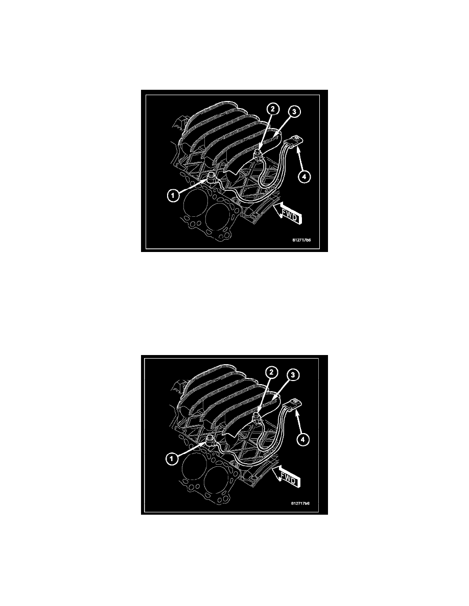
The two knock sensors (1) are bolted into the cylinder block under the intake manifold (3).
NOTE: The left sensor is identified by an identification tag (LEFT). It is also identified by a larger bolt head. The Powertrain Control Module (PCM)
must have and know the correct sensor left/right positions. Do not mix the sensor locations.
1. Disconnect knock sensor dual pigtail harness from engine wiring harness. This connection is made near rear of engine.
2. Remove intake manifold.
3. Remove sensor mounting bolts (2). Note foam strip on bolt threads. This foam is used only to retain the bolts to sensors for plant assembly. It is
not used as a sealant. Do not apply any adhesive, sealant or thread locking compound to these bolts.
4. Remove sensors from engine.
INSTALLATION
NOTE: The left sensor is identified by an identification tag (LEFT). It is also identified by a larger bolt head. The Powertrain Control Module (PCM)
must have and know the correct sensor left/right positions. Do not mix the sensor locations.
1. Thoroughly clean knock sensor mounting holes.
2. Install sensors (1) into cylinder block.
NOTE:
-
Over or under tightening the sensor mounting bolts (2) will affect knock sensor performance, possibly causing improper spark control.
Always use the specified torque when installing the knock sensors. The torque for the knock senor bolt is relatively light for an 8mm bolt.
-
Note foam strip on bolt threads. This foam is used only to retain the bolts to sensors for plant assembly. It is not used as a sealant. Do not