
Dakota 2WD V8-4.7L VIN J (2005)
6.
Remove the bolts securing the transfer case skid plate to the frame and lower the skid plate and transmission assembly approximately 51 - 102 mm
(2 - 4 in.).
7.
Loosen the skid plate to trans mount nuts (4).
8.
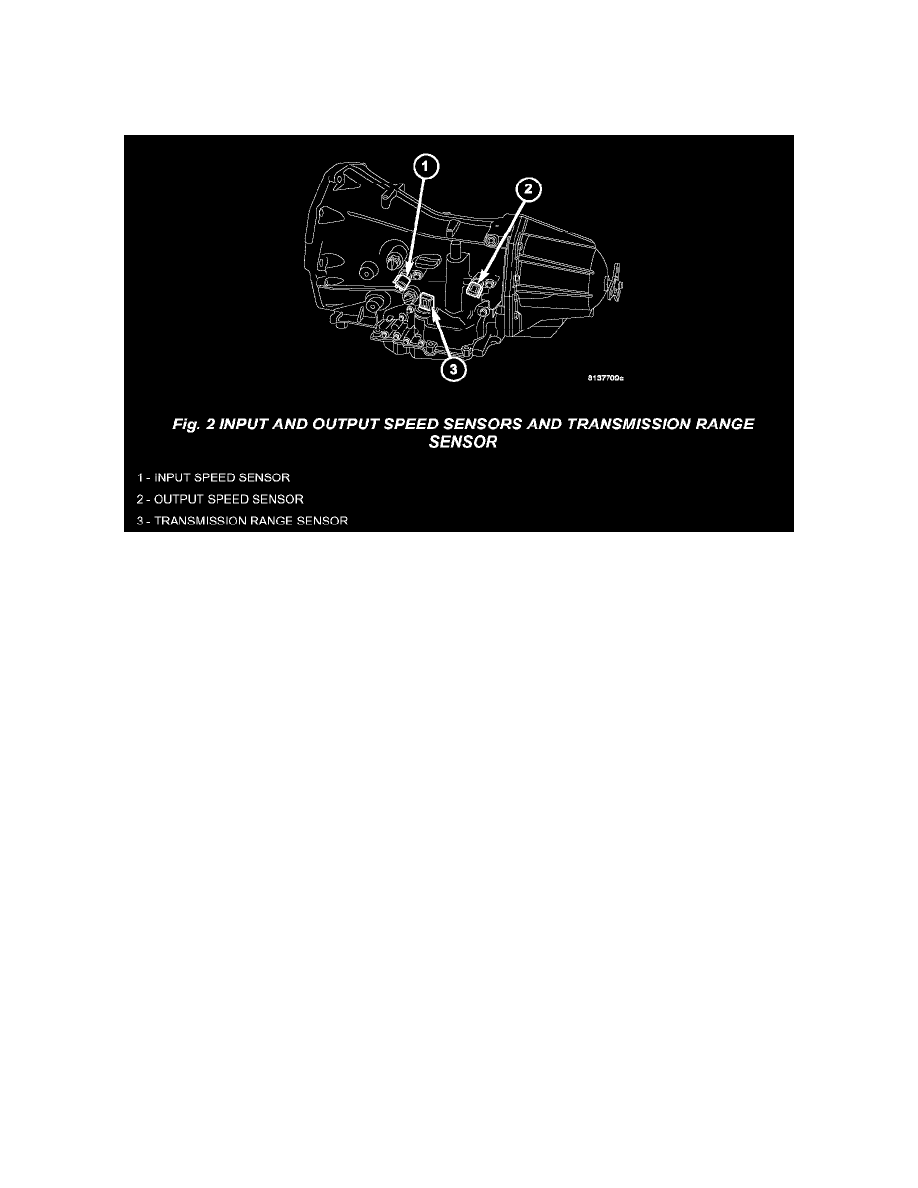
Disconnect the input speed sensor connector, output speed sensor connector, and the transmission range sensor connector (Fig. 2).
9.
Disconnect the transmission solenoid/pressure switch connector (Fig. 1).
10.
Disconnect the wiring harness routing clip at the top of the transmission. Pull the wiring harness to the driver's (left) side of the vehicle.
11.
Proceed to the WIRING HARNESS REPAIR PROCEDURE: Step # 1
12.
Reconnect the transmission solenoid/pressure switch assembly connector.
13.
Connect the input speed sensor connector, output speed sensor connector, and the transmission range sensor connector.
14.
Secure the wiring harness routing clip at the top of the transmission.
15.
Install the four bolts securing the transfer case crossmember to the vehicle. Tighten the crossmember to frame bolts to 68 N.m (50 ft.lbs.).
16.
Tighten the nuts attaching the transmission mount to the transfer case skid plate to 35 N.m (26 ft. lbs.).
17.
Install the transmission skid plate, if equipped. Tighten the crossmember to frame bolts to 74 N.m (55 ft. lbs.).
18.
Lower the vehicle.
19.
Connect the negative battery cable and reset the clock.
20.
Close the hood.
21.
Using the DRB III(R) perform the Quick Learn Procedure and verify the solenoid is operating properly.
Wiring Harness and Solenoid Repair Procedure
1.
Remove the tape from wiring harness conduit at the Solenoid/Pressure switch connector and pull the wiring out of the conduit about 4 inches from
the connector.
2.
Clearly mark the cavity locations on each wire 76 mm (3 in.) up from the transmission solenoid/pressure switch connector. Refer to the detailed
wiring and connector diagrams available in TechCONNECT under: Wiring, 21 - Transmission/Transaxle, Automatic - 42 RLE, Solenoid/Pressure
Switch Assy, Wiring Diagrams and Connector Pinout.