
Dakota 2WD V8-4.7L VIN J (2005)
c. Select "More Options".
d. Select "ECU Flash".
e. Verify the "Part Number" (displayed at the end of the "Resident flash file for" statement) has been updated to the new part number. If it has
updated, then the flash has been completed successfully.
NOTE:
On 2007 model year vehicles, if the flash was interrupted or failed the ORC module must be replaced. Continue to Section C. ORC Module
Replacement
10. Clear any Diagnostic Trouble Codes (DTCs) as follows:
NOTE:
Due to the ORC programming procedure, DTC(s) may be set in other modules (TCM, ABS, BCM, MIC, WCM, etc.) within the vehicle, if so
equipped. Some DTC's may cause the MIL to illuminate.
a. From the "Home" screen select "System View".
b. Select "All DTCs".
c. Press "Clear All Stored DTCs" if there are any DTCs shown on the list.
11. Turn the ignition key to the "OF" position and remove the StarMOBILE unit, StarMOBILE vehicle cable, and battery charger from the vehicle.
C. ORC Module Replacement
NOTE:
The Occupant Restraint Controller (ORC) Module is not "abort-recoverable." Should the reprogramming process be interrupted or fail, the ORC
module must be replaced.
CAUTION:
The replacement ORC module does not require reprogramming. The latest available software has already been programmed into the new ORC
module.
1. Disconnect and isolate the battery negative cable. Wait two minutes for the system capacitor to discharge before further service.
WARNING:
To avoid serious or fatal injury on vehicles equipped with airbags, disable the Supplemental Restraint System (SRS) before attempting this
procedure. Disconnect and isolate the battery negative (ground) cable, then wait two minutes for the system capacitor to discharge before continuing.
This is the only sure way to disable the SRS. Failure to take the proper precautions could result in accidental airbag deployment.
2. Partially rollback the carpet to gain access to the floor distribution duct and the ORC module.
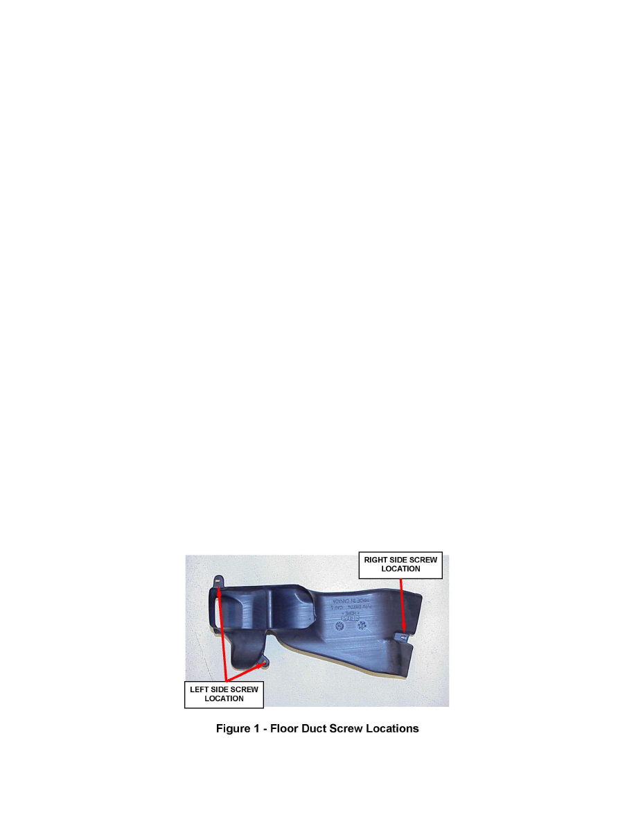
3. Remove the three floor distribution duct retaining screws. Two of the screws are accessed from the left side of the vehicle and one from the right side
of the vehicle. (Figure 1).