
Dakota 2WD V8-4.7L VIN J (2005)
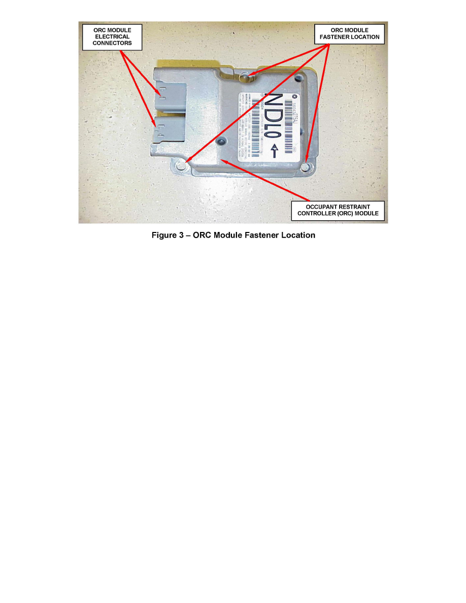
6. Remove the three nuts that secure the ORC to the studs of the ORC mount welded onto the top of the floor panel transmission tunnel (Figure 3).
7. Remove the ORC from the ORC mount.
8. Carefully position the ORC onto the studs of the ORC mount on the floor panel transmission tunnel. When the ORC is correctly positioned, the arrow
on the ORC label will be pointed forward in the vehicle and the ORC connector receptacles will be facing the left side of the vehicle (Figure 3).
WARNING:
To avoid personal injury or death, never strike or drop the ORC, as it can damage the impact sensor or affect its calibration. The ORC contains the
impact sensor, which enables the system to deploy the supplemental restraints. If an occupant restraint controller is accidentally dropped during
service, the module must be scrapped and replaced with a new unit. Failure to observe this warning could result in accidental, incomplete, or
improper supplemental restraint deployment.
9. Install and tighten the three nuts that secure the ORC to the studs of the ORC mount that is welded onto the floor panel transmission tunnel. Tighten
the nuts to 50 in. lbs. (6 N.m).
10. Reconnect the instrument panel and body wire harness connectors to the ORC connector receptacles located on the left facing side of the module.
Be certain that the latches and the red CPA locks on both connectors are each fully engaged.
11. Reinstall the floor distribution duct onto the bottom of the heater-air conditioner housing.
12. Do not reconnect the battery negative cable at this time. Perform the supplemental restraint system verification test using the following procedure:
a. During the test, the negative battery cable remains disconnected and isolated, as it was during the supplemental restraint system component
removal and installation procedures.
b. Be certain that the diagnostic scan tool contains the latest version of the proper diagnostic software. Connect the scan tool to the 16-way Data
Link Connector (DLC). The DLC is located on the driver side lower edge of the instrument panel, outboard of the steering column.
c. Turn the ignition switch to the "ON" position and exit the vehicle with the scan tool.
d. Check to be certain that nobody is in the vehicle, then reconnect the negative battery cable.
e. Using the scan tool, read and record the active (current) Diagnostic Trouble Code (DTC) data.
f.
Next, use the scan tool to read and record any stored (historical) DTC data.
g. Use the scan tool to erase the stored DTC data.