
Dakota 4WD V6-3.9L VIN X (1997)
interpreted by the CAB. It then compares the frequency of the sine wave to a time value to calculate vehicle speed. The CAB continues to monitor the
frequency to determine a deceleration rate that would indicate a possible wheel locking tendency.
The signal strength of any magnetic induction sensor is directly affected by:
-
Magnetic field strength; the stronger the magnetic field, the stronger the signal.
-
Number of windings in the sensor; more windings provide a stronger signal.
-
Exciter ring speed; the faster the exciter ring rotates, the stronger the signal will be.
-
Distance between the exciter ring teeth and WSS; the closer the WSS is to the exciter ring, the stronger the signal will be.
The WSS is not adjustable. A clearance specification has been established for manufacturing tolerances. If the clearance is not within these
specifications, then either the WSS or other components may be damaged. The clearance between the WSS and the exciter ring is 0.005 to 0.050 inch.
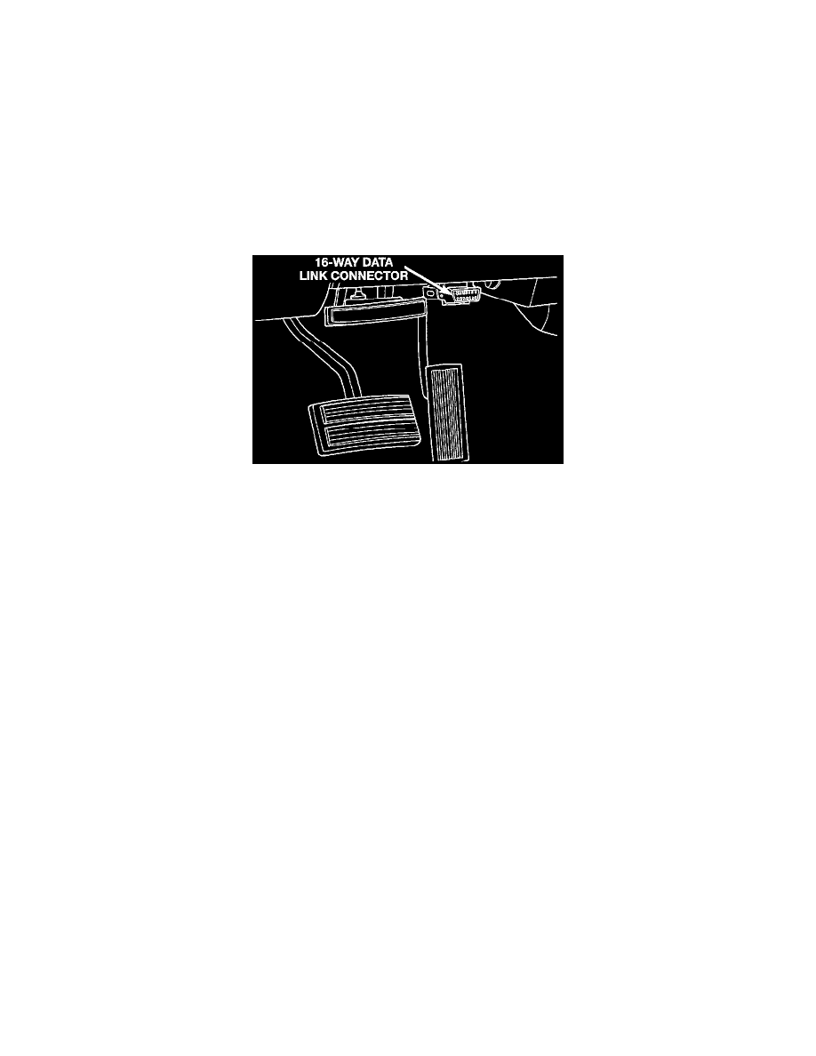
The assembly plant performs a "rolls Test" on every vehicle that leaves the assembly plant. One of the test performed is a test of the WSS. To properly
test the sensor, the assembly plant connects test equipment to the Data Link Connector (DLC). This connector is located to the left of the steering
column and attached to the lower portion of the instrument panel.
Data Link Connector (DLC)
The rolls test terminal is spliced to the WSS circuit. The vehicle is then driven on a set of rollers and the WSS output is monitored for proper operation.
CIRCUIT OPERATION
The rear wheel speed sensor is mounted on the top of the rear axle differential. The sensor converts wheel speed into an electrical signal that is
transmitted to the Controller, Antilock Brakes (CAB).
Circuits B113 and B114, a pair of twisted wires, connect to the sensor and provide signals to the CAB.
Circuit B113 connects to cavity 14 of the CAB. Circuit B114 connects to cavity 13 of the CAB.