
Dakota 4WD V8-318 5.2L (1991)
2.
Remove three screws retaining bearing housing to lock housing. These screws must be removed before steering shaft is removed.
3.
Remove bearing housing from shaft, and then the coil spring.
4.
Remove lock plate from shaft, then remove shaft through lower end of column.
LOCK HOUSING
1.
If equipped with shift indicator dial, remove pointer screw and position pointer aside.
2.
If equipped, remove screw and lift out buzzer switch.
3.
Remove two retaining screws and lock lever guide plate to expose the lock cylinder release hole.
4.
Place cylinder in Lock position and remove key. Insert a small screwdriver into lock cylinder release hole and push in to release spring loaded lock
retainer, while pulling lock cylinder out of the housing.
5.
Remove the three retaining screws and ignition switch assembly.
6.
Grasp lock lever and spring assembly and pull straight out of housing.
7.
Remove the four lock housing to column jacket hex retaining screws and remove housing from jacket.
SHIFT TUBE
1.
On Ramcharger and D/W-100-350 series models with automatic transmission, loosen shift tube setscrew in shift housing and remove shift
tube through lower end of jacket.
2.
On Van and Wagon models with automatic transmission, remove indicator bracket and then the shift tube through the lower end of the jacket.
3.
On Van and Wagon models with manual transmission, remove the three bearing support screws at lower end of jacket and the three adjustable
bushing screws from cam slots in jacket, then remove shift tube and lever assembly through lower end of jacket.
4.
On all models, remove floor plate and grommet from jacket.
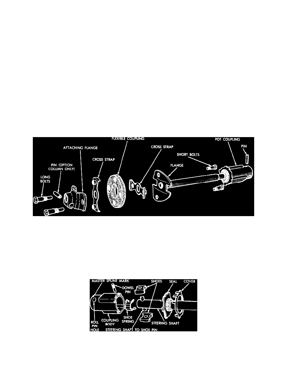
Fig. 12 Steering shaft flex coupling exploded view
STEERING SHAFT FLEX COUPLING
1.
Remove the four bolts and two cross straps.
2.
Remove flex coupling.
3.
Check coupling and cross straps for cracks, warpage or distortion. Replace as required.
4.
Position flex coupling in the two cross straps, then install two long and short attaching bolts. Ensure master spline on steering shaft lines up with
master spline in lower pot coupling during assembly.
5.
Torque coupling attaching bolts to 200 inch lbs.
Fig. 13 Steering shaft pot coupling exploded view
STEERING SHAFT POT COUPLING