
Dakota 4WD V8-4.7L (2009)
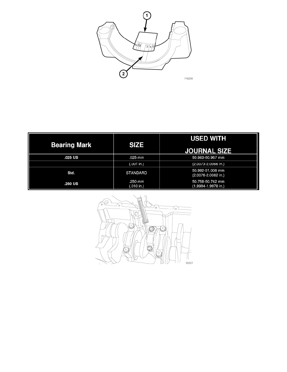
5. Install bearing cap and connecting rod on the journal and tighten bolts to 27 Nm (20 ft. lbs.) plus a 90° turn. DO NOT rotate crankshaft. Plastigage
will smear, resulting in inaccurate indication.
6. Remove the bearing cap and determine amount of bearing-to-journal clearance by measuring the width of compressed Plastigage (2). Refer to
Engine Specifications for the proper clearance. Plastigage should indicate the same clearance across the entire width of the insert. If the
clearance varies, it may be caused by either a tapered journal, bent connecting rod or foreign material trapped between the insert and
cap or rod.
7. If the correct clearance is indicated, replacement of the bearing inserts is not necessary. Remove the Plastigage (2) from crankshaft journal and
bearing insert. Proceed with installation.
8. If bearing-to-journal clearance exceeds the specification, determine which service bearing set to use, using the chart above.
CAUTION: Connecting Rod Bolts are Torque to Yield Bolts and Must Not Be Reused. Always replace the Rod Bolts whenever they are
loosened or removed.
9. Repeat the Plastigage measurement to verify your bearing selection prior to final assembly.
10. Once you have selected the proper insert, install the insert and cap. Tighten the connecting rod bolts to 27 Nm (20 ft. lbs.) plus a 90° turn.
Slide snug-fitting feeler gauge between the connecting rod and crankshaft journal flange. Refer to Engine Specifications for the proper clearance.
Replace the connecting rod if the side clearance is not within specification.