
Dakota 4WD V8-4.7L VIN N (2000)
Antenna: Testing and Inspection
WARNING: ON VEHICLES EQUIPPED WITH AIR-BAGS, REFER TO AIRBAGS AND SEAT BELTS/AIRBAGS BEFORE
ATTEMPTING ANY STEERING WHEEL, STEERING COLUMN, OR INSTRUMENT PANEL COMPONENT DIAGNOSIS OR SERVICE.
FAILURE TO TAKE THE PROPER PRECAUTIONS COULD RESULT IN ACCIDENTAL AIR-BAG DEPLOYMENT AND POSSIBLE
PERSONAL INJURY.
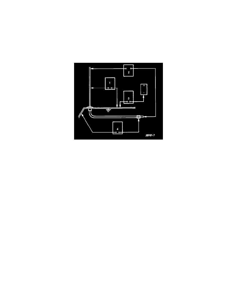
The following four tests are used to diagnose the antenna with an ohmmeter:
-
Test 1 -Mast to ground test
-
Test 2 -Tip-of-mast to tip-of-conductor test
-
Test 3 -Body ground to battery ground test
-
Test 4 -Body ground to coaxial shield test.
Antenna Tests
The ohmmeter test lead connections for each test are shown in Antenna Tests.
NOTE:
-
This model has a special coating on the antenna mast which is not electrically conductive. Remove the antenna mast from the antenna base before
attempting to perform Tests 1 and 2.
-
This model has a two-piece antenna coaxial cable. Tests 2 and 4 must be conducted in two steps to isolate a coaxial cable problem; from the
coaxial cable connection under the right end of the instrument panel near the inboard side of the glove box opening to the antenna base, and then
from the coaxial cable connection to the radio chassis connection.
TEST 1
Test 1 determines if the antenna mast is insulated from the base. Proceed as follows:
1. Disconnect the antenna coaxial cable connector from the radio receiver chassis and isolate. Remove the antenna mast from the antenna base.
2. Insert one ohmmeter test lead into the socket for the antenna mast in the center of the antenna base. Connect the other test lead to the perimeter of
the antenna base. Check for continuity.
3. There should be no continuity. If continuity is found, replace the faulty or damaged antenna base and cable assembly.
TEST 2
Test 2 checks the antenna for an open circuit as follows:
1. Disconnect the antenna coaxial cable connector from the radio receiver chassis. Remove the antenna mast from the antenna base.
2. Insert one ohmmeter test lead into the socket for the antenna mast in the center of the antenna base. Connect the other test lead to the center pin of
the antenna coaxial cable connector.
3. Continuity should exist (the ohmmeter should only register a fraction of an ohm). High or infinite resistance indicates damage to the base and cable
assembly. Replace the faulty base and cable, if required.
TEST 3
Test 3 checks the condition of the vehicle body ground connection. This test should be performed with the battery positive cable removed from the
battery. Disconnect both battery cables, the negative cable first. Reconnect the battery negative cable and perform the test as follows:
1. Connect one ohmmeter test lead to the vehicle fender. Connect the other test lead to the battery negative terminal post.
2. The resistance should be less than one ohm.
3. If the resistance is more than one ohm, check the braided ground strap(s) connected to the engine and the vehicle body for being loose, corroded,
or damaged. Repair the ground strap connections, if required.