
Dakota 4WD V8-4.7L VIN N (2000)
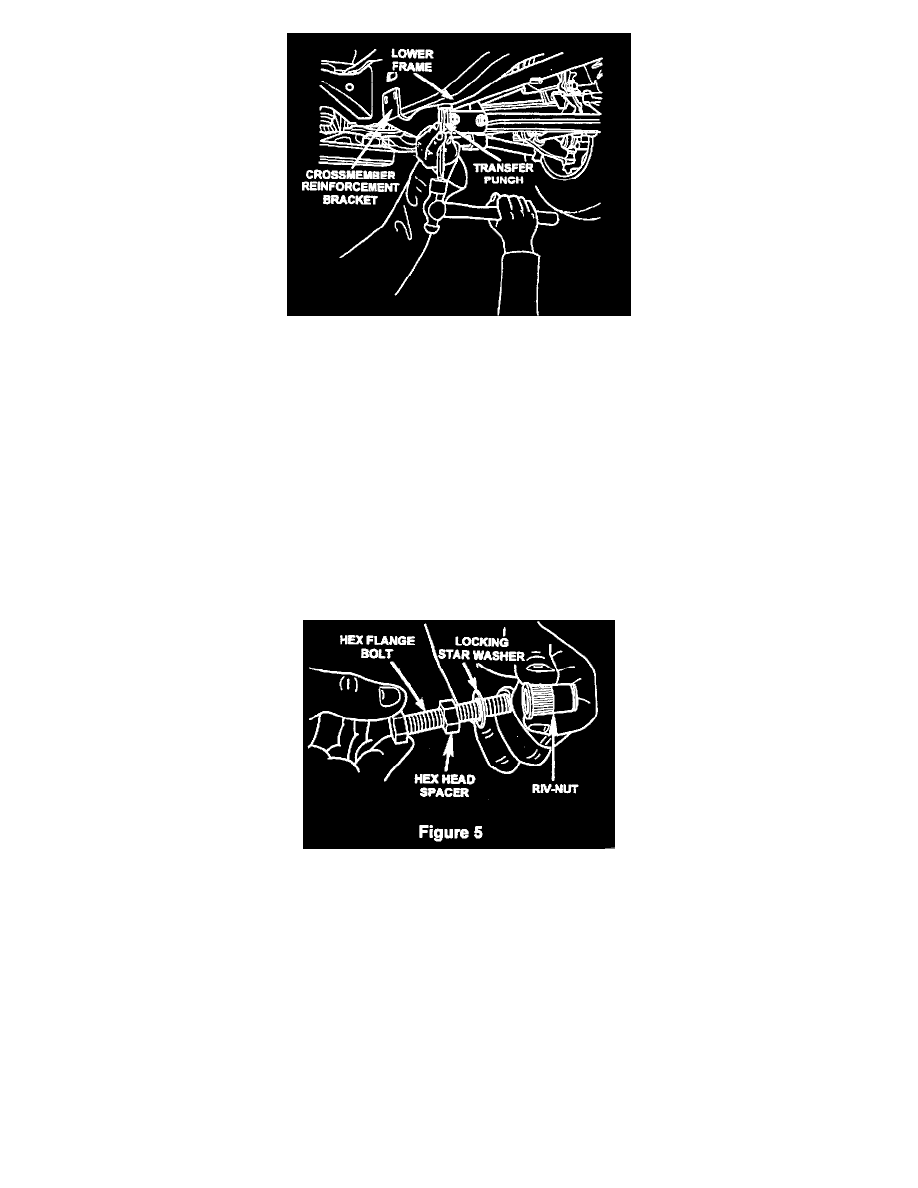
Figure 4
8. Hold the reinforcement bracket tight against the bottom of the frame. Using the supplied transfer punch and reinforcement bracket lower holes as a
template, center punch the bottom of the frame for the two (2) lower Riv-Nut locations (Figure 4).
CAUTION:
Do not center punch the frame side Riv-Nut locations at this time.
9. Remove the reinforcement bracket.
10. Using the center punch marks as a guide, drill two (2) V4 inch pilot holes through the lower frame.
11. Enlarge the two (2) ¼ inch pilot holes in the lower frame with the 45/64 inch drill bit supplied.
12. Clean off any burrs around the two (2)45/64 inch holes with a flat file and apply a coat of zinc primer (PN 4443636) or equivalent to cover the edges
of all drilled holes.
Figure 5
13. Assemble the Riv-Nut installation tool by installing the hex head spacer onto the M12 x 4Srnmghex flange bolts. Then install the locking star washer
onto the bolt. Screw the installation tool into one of the Riv-Nuts (Figure 5).
CAUTION:
A light coat of motor oil must be applied to the hex flange bolt head, hex head spacer and the hex flange bolt threads before installing each Riv-Nut
(Figure 5). Failure to apply oil to these components will cause false torque readings and incorrect Riv-Nut crush.
NOTE:
One of the M12 x 45mm hex flange bolts is provided and must be used as the tool to install all of the Riv-Nuts. Do not use any of the other eight
bolts to install Riv-Nuts.
14.
Place the Riv-Nut (with installation tool) into one of the 45/64 inch holes drilled into the lower section of the frame.