
Service Procedures for Drive/Propeller Shaft on Dakota 4WD V8-47L VIN N (2000) - Page 4437
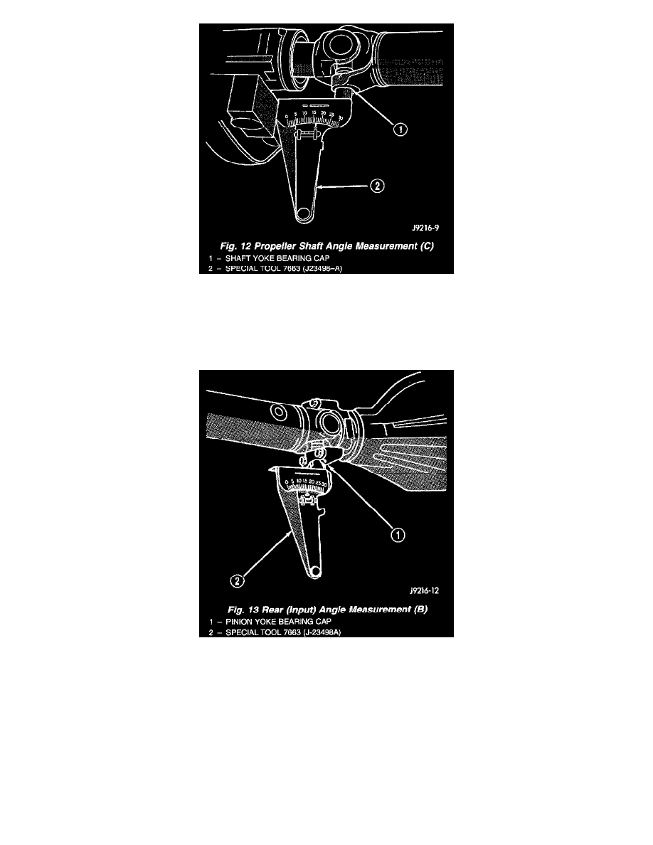
Fig. 12
3. Rotate propeller shaft 90° and place Inclinometer on yoke bearing cap parallel to the shaft (Fig. 12). Center bubble in sight glass and record
measurement. This measurement can also be taken at the rear end of the shaft.
This measurement will give you the propeller shaft angle (C).
4. Subtract smaller figure from larger (C minus A) to obtain transmission output operating angle.
Fig. 13
5. Rotate propeller shaft 90° and place Inclinometer on pinion yoke bearing cap parallel to the shaft (Fig. 13). Center bubble in sight glass and record
measurement.
This measurement will give you the pinion shaft or input yoke angle (B).
6. Subtract smaller figure from larger (C minus B) to obtain axle Input Operating Angle.