
Dakota Quad Cab 2WD V8-4.7L VIN N (2001)
Hazard Warning Switch: Description and Operation
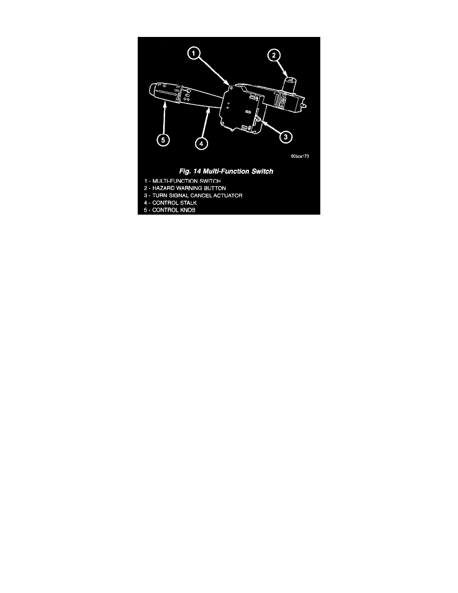
Fig.14 Multi-Function Switch
MULTI-FUNCTION SWITCH
The multi-function switch is secured with two screws to the multi-function switch mounting housing on the left side of the steering column, just
below the steering wheel. The only visible parts of the multi-function switch are the control stalk that extends through a dedicated opening in the
left side of the upper steering column shrouds, and the hazard warning switch push button that protrudes through an opening in the upper steering
column shroud on the top of the steering column. The remainder of the switch, its mounting provisions, and its electrical connections are all
concealed beneath the steering column shrouds. The multi-function switch control stalk has both nomenclature and International Control and
Display Symbol graphics applied to it, which identify its many functions. An International Control and Display Symbol icon for "Hazard Warning"
is applied to the top of the hazard warning switch push button.
The switch housing and its controls are constructed of molded black plastic. A single connector receptacle connects the switch to the vehicle
electrical system through a take out and connector of the instrument panel wire harness.
The multi-function switch supports the following functions and features:
-
Continuous Wipe Modes - The control knob of the multi-function switch provides two continuous wipe switch positions, low speed or high
speed.
-
Hazard Warning Control - The internal circuitry and hardware of the multi-function switch provide detent switching for activation and
deactivation of the hazard warning system.
-
Headlamp Beam Selection - The internal circuitry and hardware of the multi-function switch provide detent switching for selection of the
headlamp high or low beams.
-
Headlamp Optical Horn - The internal circuitry and hardware of the multi-function switch includes momentary switching of the headlamp high
beam circuits to provide an optical horn feature (sometimes referred to as flash-to-pass), which allows the vehicle operator to momentarily
flash the headlamp high beams as an optical signalling device.
-
Intermittent Wipe Mode - The control knob of the multi-function switch provides an intermittent wipe mode with multiple delay interval
positions.
-
Turn Signal Control - The internal circuitry and hardware of the multi-function switch provide both momentary non-detent switching and
detent switching with automatic cancellation for both the left and right turn signals.
-
Washer Mode - The control knob of the multi-function switch provides washer system operation when the knob is depressed towards the
steering column.
The multi-function switch cannot be adjusted or repaired. If any function of the switch is faulty, or if the switch is damaged, the entire switch unit
must be replaced.
The multi-function switch uses conventionally switched outputs and a variable resistor to control the many functions and features it provides using
hard wired circuitry. The switch is grounded at all times through a single wire take out with an eyelet terminal connector of the instrument panel
wire harness that is secured by a nut to a ground stud located on the left cowl side inner panel, near the left instrument panel end bracket. When the
ignition switch is in the Accessory or ON positions, battery current from a fuse in the Junction Block (JB) is provided through a fused ignition
switch output (run-acc) circuit. Following are descriptions of how the multi-function switch operates to control the many functions and features it
provides:
-
Continuous Wipe Modes - When the control knob of the multi-function switch is rotated to the High or Low positions, the circuitry within the