
Dakota Quad Cab 2WD V8-5.9L VIN Z LDC (2002)
Horn Relay: Testing and Inspection
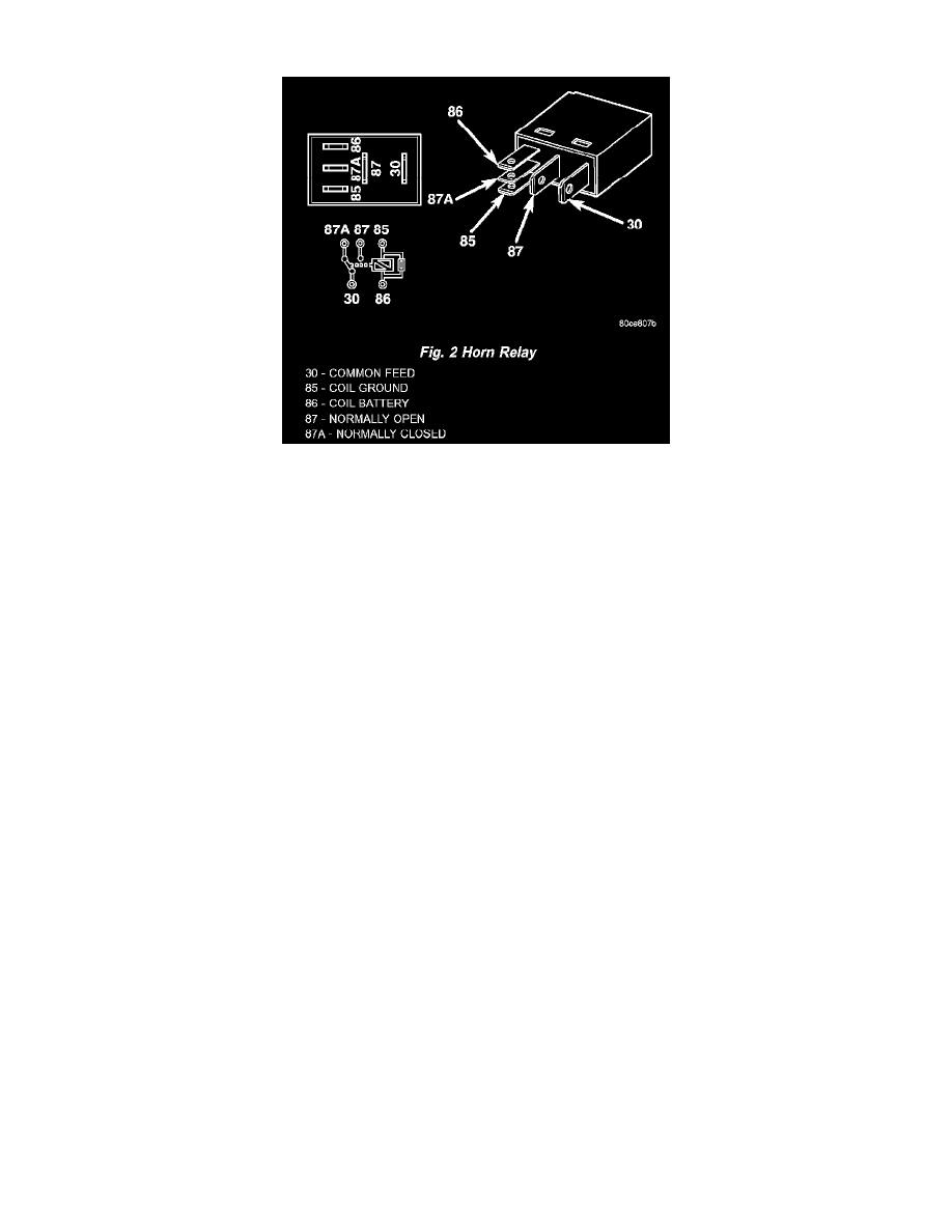
Fig. 2 Horn Relay
The horn relay is located in the Junction Block (JB) on the left end of the instrument panel in the passenger compartment of the vehicle. If a problem is
encountered with a continuously sounding horn, it can usually be quickly resolved by removing the horn relay from the JB until further diagnosis is
completed. See the fuse and relay layout label affixed to the inside surface of the fuse access panel for horn relay identification and location.
1. Remove the horn relay from the JB. (Refer to HORN RELAY - REMOVAL) for the procedures.
2. A relay in the de-energized position should have continuity between terminals 87A and 30, and no continuity between terminals 87 and 30. If OK,
go to Step 3. If not OK, replace the faulty relay.
3. Resistance between terminals 85 and 86 (electromagnet) should be 75 ± 5 ohms. If OK, go to Step 4. If not OK, replace the faulty relay.
4. Connect a battery to terminals 85 and 86. There should now be continuity between terminals 30 and 87, and no continuity between terminals 87A
and 30. If OK, perform the Relay Circuit Test that follows. If not OK, replace the faulty relay
Relay Circuit Test
1. The relay common feed terminal cavity (30) is connected to battery voltage and should be hot at all times. If OK, go to Step 2. If not OK, repair
the open circuit to the fuse in the PDC as required.
2. The relay normally closed terminal (87A) is connected to terminal 30 in the de-energized position, but is not used for this application. Go to Step
3.
3. The relay normally open terminal (87) is connected to the common feed terminal (30) in the energized position. This terminal supplies battery
voltage to the horn(s). There should be continuity between the cavity for relay terminal 87 and the horn relay output circuit cavity of each horn
wire harness connector at all times. If OK, go to Step 4. If not OK, repair the open circuit to the horn(s) as required.
4. The coil battery terminal (86) is connected to the electromagnet in the relay It is connected to battery voltage and should be hot at all times. Check
for battery voltage at the cavity for relay terminal 86. If OK, go to Step 5. If not OK, repair the open circuit to the fuse in the PDC as required.
5. The coil ground terminal (85) is connected to the electromagnet in the relay. It is grounded through the horn switch when the horn switch is
depressed. On vehicles equipped with the Remote Keyless Entry (RKE) system, the horn relay coil ground terminal can also be grounded by the
Central Timer Module (CTM) in response to certain inputs related to the RKE system or the Vehicle Theft Security System. Check for continuity
to ground at the cavity for relay terminal 85. There should be continuity with the horn switch depressed, and no continuity with the horn switch
released. If not OK, (Refer to HORN SWITCH - DIAGNOSIS AND TESTING).