
Dakota Quad Cab 2WD V8-5.9L VIN Z LDC (2002)
Hazard Warning Switch: Description and Operation
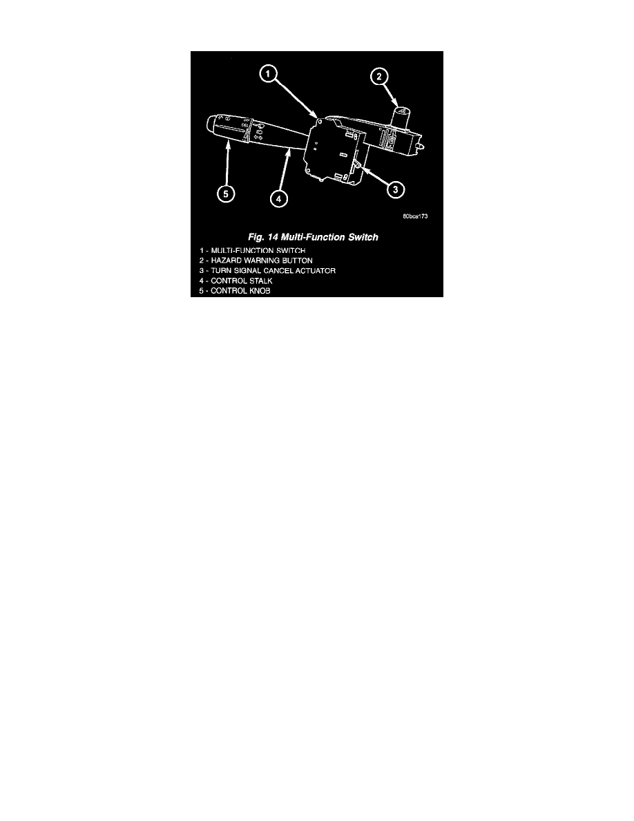
Fig.14 Multi-Function Switch
MULTIFUNCTION SWITCH
The multi-function switch is secured with screws to the multi-function switch mounting housing on the left side of the steering column..The switch,
its mounting provisions, and its electrical connections are all concealed beneath the steering column shrouds.
A single connector connects the switch to the vehicle electrical system.
The multi-function switch supports the following functions and features:
-
Continuous Wipe Modes
-
Hazard Warning Control
-
Headlamp Beam Selection
-
Headlamp Optical Horn
-
Intermittent Wipe Mode
-
Turn Signal Control
-
Washer Mode
The multi-function switch cannot be adjusted or repaired. If any function of the switch is faulty, or if the switch is damaged, the entire switch unit
must be replaced.
The multi-function switch uses conventionally switched outputs and a variable resistor to control the many functions and features it provides using
hard wired circuitry The switch is grounded to the chassis near the left instrument panel end bracket. When the ignition switch is in the Accessory
or ON positions, battery voltage is provided through a fused ignition switch output (RUN/ACC) circuit. Following are descriptions of how the
multi-function switch operates to control the many functions and features it provides:
-
Continuous Wipe Modes - When the control knob of the multi-function switch is rotated to the High or Low positions, the switch provides a
battery voltage output directly to the high or low speed brush of the wiper motor. When the control knob is in the Off position, the switch
connects the output of the wiper motor park switch to the low speed brush of the wiper motor.
-
Hazard Warning Control - The hazard warning push button is pushed down to activate the hazard warning system, and pushed down again to
turn the system off. The hazard warning circuitry provides a signal to the hazard warning sense of the combination flasher to activate or
deactivate the flasher output to the warning lamps.
-
Headlamp Beam Selection - The multi-function switch control stalk is pulled towards the steering wheel past a detent, then released to actuate
the headlamp beam selection switch. Each time the control stalk is actuated in this manner, the opposite headlamp mode from what is currently
selected will be activated. The headlamp beam selection switch directs a ground signal output from the headlamp switch to the appropriate low
beam or high beam sense of the Central Timer Module (CTM). The CTM then controls a hard wired output to activate the selected headlamp
beams.
-
Headlamp Optical Horn - The left multi-function switch control stalk is pulled towards the steering wheel to just before a detent, to
momentarily activate the headlamp high beams. The high beams will remain illuminated until the control stalk is released. The headlamp beam
selection switch provides a momentary ground path to the CTM high beam sense.
-
Intermittent Wipe Mode - When the multi-function switch control knob is rotated to the Delay position, the switch provides a battery current
signal to the Central Timer Module (CTM). If the Delay mode is selected, the control knob can then be rotated to multiple minor detent
positions, which actuates a variable resistor within the switch and provides a hard wired output to the CTM that signals the desired delay
interval for the intermittent wiper feature.