
Dakota Quad Cab 4WD V6-3.9L VIN X (2001)
Glove Compartment: Service and Repair
Glove Box Latch Replacement
DISASSEMBLY
The glove box latch and handle unit of the glove box used in this vehicle is serviced individually. Following are the procedures for disassembling this
component from the glove box module.
WARNING: ON VEHICLES EQUIPPED WITH AIR-BAGS, DISABLE THE AIRBAG SYSTEM BEFORE ATTEMPTING ANY
STEERING WHEEL, STEERING COLUMN, SEAT BELT TENSIONER, OR INSTRUMENT PANEL COMPONENT DIAGNOSIS OR
SERVICE. DISCONNECT AND ISOLATE THE BATTERY NEGATIVE (GROUND) CABLE, THEN WAIT TWO MINUTES FOR THE
AIRBAG SYSTEM CAPACITOR TO DISCHARGE BEFORE PERFORMING FURTHER DIAGNOSIS OR SERVICE. THIS IS THE ONLY
SURE WAY TO DISABLE THE AIRBAG SYSTEM. FAILURE TO TAKE THE PROPER PRECAUTIONS COULD RESULT IN
ACCIDENTAL AIRBAG DEPLOYMENT AND POSSIBLE PERSONAL INJURY.
1. Remove the glove box module from the instrument panel. See: Glove Box
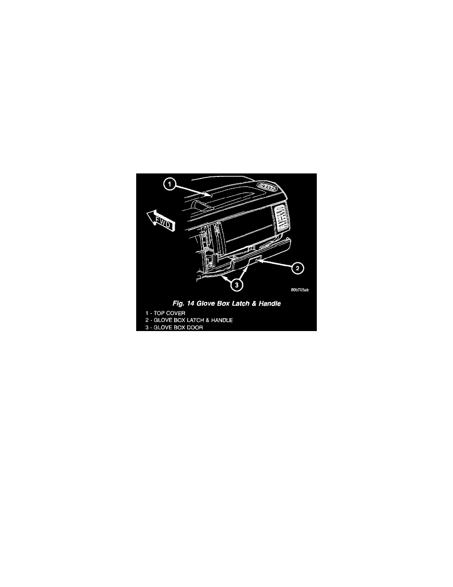
2. Remove the nine screws that secure the flanges around the perimeter of the glove box bin to the inside of the glove box door.
Fig. 14 Glove Box Latch & Handle
3. Remove the glove box bin from the inside of the glove box door.
4. Remove the two screws that secure the glove box latch and handle to the inside of the glove box door.
5. Remove the glove box latch and handle from the inside of the glove box door.
ASSEMBLY
The glove box latch and handle unit of the glove box used in this vehicle is serviced individually. Following are the procedures for assembling this
component to the glove box module.
WARNING: ON VEHICLES EQUIPPED WITH AIR-BAGS, DISABLE THE AIRBAG SYSTEM BEFORE ATTEMPTING ANY
STEERING WHEEL, STEERING COLUMN, SEAT BELT TENSIONER, OR INSTRUMENT PANEL COMPONENT DIAGNOSIS OR
SERVICE. DISCONNECT AND ISOLATE THE BATTERY NEGATIVE (GROUND) CABLE, THEN WAIT TWO MINUTES FOR THE
AIRBAG SYSTEM CAPACITOR TO DISCHARGE BEFORE PERFORMING FURTHER DIAGNOSIS OR SERVICE. THIS IS THE ONLY
SURE WAY TO DISABLE THE AIRBAG SYSTEM. FAILURE TO TAKE THE PROPER PRECAUTIONS COULD RESULT IN
ACCIDENTAL AIRBAG DEPLOYMENT AND POSSIBLE PERSONAL INJURY.
1. Position the glove box latch and handle to the inside of the glove box door.
2. Install and tighten the two screws that secure the glove box latch and handle to the inside of the glove box door. Tighten the screws to 2 N.m (20
in. lbs.).
3. Position the glove box bin to the inside of the glove box door.
4. Install and tighten the nine screws that secure the flanges around the perimeter of the glove box bin to the inside of the glove box door. Tighten the
screws to 2 N.m (20 in. lbs.).
5. Reinstall the glove box module onto the instrument panel. See: Glove Box