
Dakota R/T 2WD V8-5.9L VIN Z LDC (1999)
9.
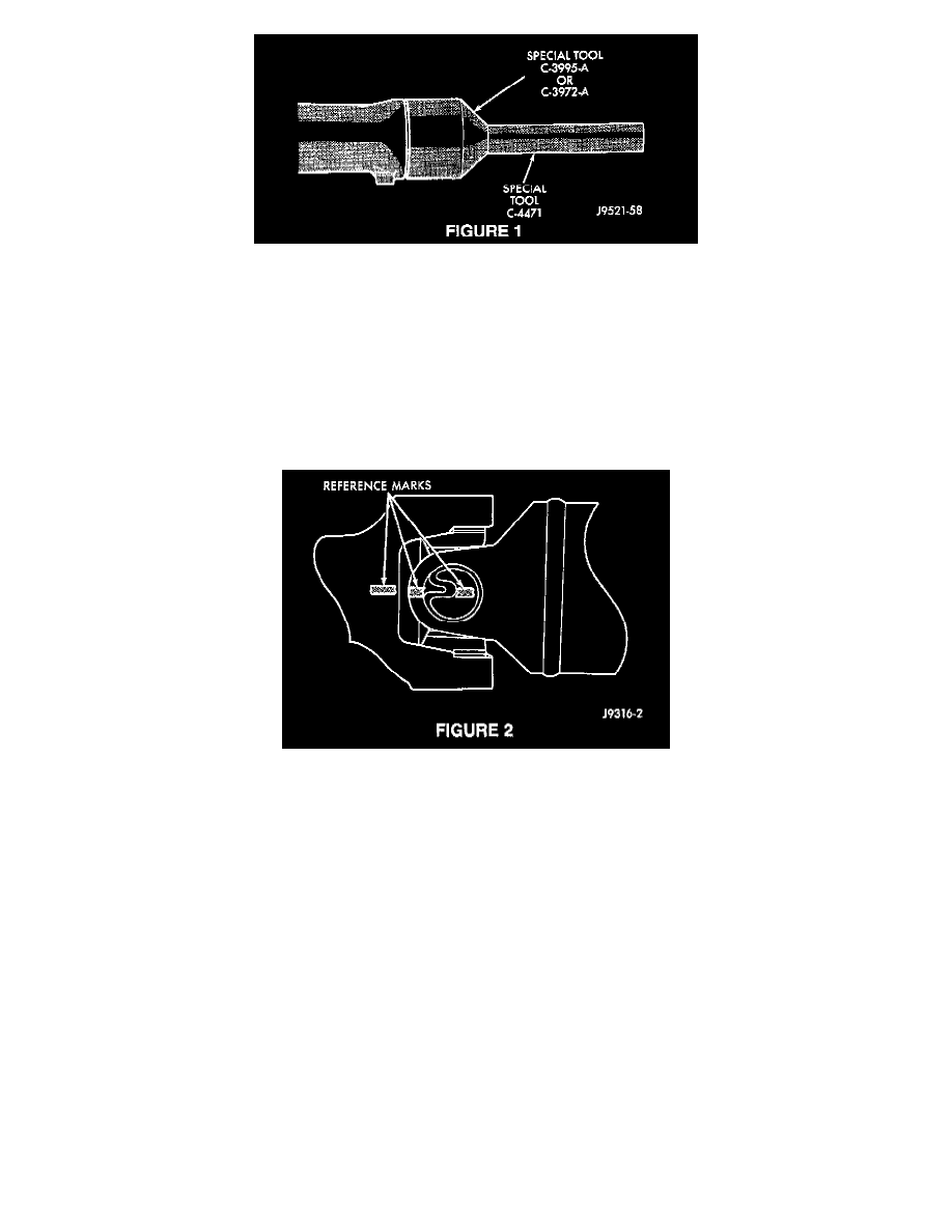
Install new transmission extension housing seal p/n 04531216 into the extension housing using Special Tool C-3995-A (seal installer) (Figure 1).
NOTE:
THE NEXT STEPS OF THE PROCEDURE WILL ALLOW FOR INDEXING OF THE NEW PROPELLER SHAFT.
10.
Using a paint pen or equivalent, place tour marks, equally spaced (00, 900, 1800, and 2700 positions) on the vibration dampener of the new
propeller shaft p/n 52105950AA. Then, number the marks 1 through 4 in order.
11.
With the number "1" identification mark facing straight down, slide the slip yoke of the new propeller shaft onto the transmission output shaft.
12.
Position the universal joint into the axle yoke. Install the universal joint strap and bolts. Tighten the bolts to 19 N.m (14 ft. lbs.).
13.
Using a paint pen or equivalent, place a line across the axle pinion yoke and the propeller shaft yoke for installation reference later in the
procedure (Figure 2).
14.
Start the engine, place the transmission gear selector into DRIVE, and then SLOWLY accelerate until maximum driveline vibration has been
identified. Note the vehicle speed at which the vibration occurs and the amplitude of the vibration.
NOTE:
IT IS RECOMMENDED THAT SPECIAL TOOL 0T38793 (ELECTRONIC VIBRATION ANALYZER) BE USED TO HELP IDENTIFY THE
AMPLITUDE OF DRIVELINE VIBRATIONS
15.
Remove the bolts holding the universal joint clamps to the pinion yoke.
16.
Rotate the propeller shaft until the number "1" is facing straight down.
17.
Carefully slide the propeller shaft off of the transmission output shaft. Rotate the propeller shaft 900 until the number "2" is facing straight down.
Then, slide the slip yoke of the propeller shaft onto the transmission output shaft.
18.
Position the universal joint into the axle yoke. Install the universal joint strap and bolts. Tighten the bolts to 19 N.m (14 ft. lbs.).
NOTE:
MAINTAIN THE SAME AXLE PINION YOKE AND PROPELLER SHAFT YOKE ORIENTATION BY ALIGNING THE SCRIBED
REFERENCE MARKS CREATED IN STEP 13.
19.
Repeat Step 14 noting whether or not the vibration increased or decreased.