
Daytona L4-153 2.5L SOHC VIN B (1993)
Brake Bleeding: Service and Repair
Antilock Brake System Bleeding Procedures
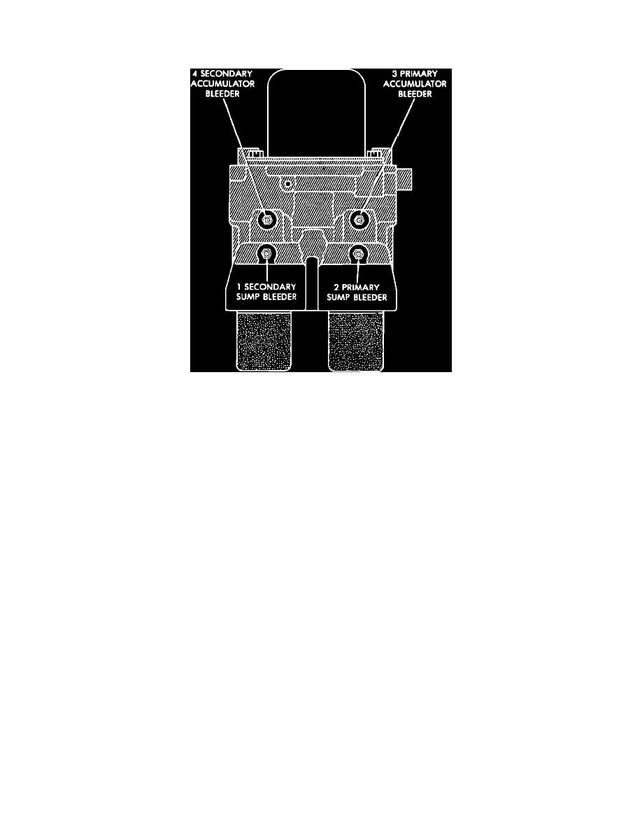
Fig. 39 Bleeding ABS Modulator Assembly
The Anti-lock Brake System (ABS) must be bled anytime air is permitted to enter the hydraulic system. If the modulator assembly is removed from the
vehicle. Both the hydraulic and ABS systems will have to be bled. The ABS system must be bled separately from the hydraulic portion of the braking
system, using a DRB II tester.
During bleeding procedures, ensure that the brake fluid level remains close to the full level in the reservoir. Check the fluid periodically during the
bleeding procedure.
When bleeding the modulator assembly wear safety glasses. A bleed tube should be attached to the bleeder screws, to direct flow of brake fluid
away from the painted surfaces of the vehicle. Brake fluid at high pressure may come out of the bleeder screws when they are opened.
The modulator assembly must be bled in the following sequence; No. 1 secondary sump, No. 2 primary sump, No. 3 primary accumulator and No. 4
secondary accumulator. To ensure proper operation of the ABS system.
1.
Remove battery to gain access to modulator assembly No. 4 bleeder screws, then connect a battery to the vehicle using jumper cables.
2.
Connect DRB II to diagnostic connector and ensure that CAB has no fault codes stored in its memory.
3.
Attach bleeder tube to secondary sump bleeder screw.
4.
Use a pressure bleeder, or with the aid of an assistant, apply light and constant pressure on the brake pedal.
5.
Loosen secondary sump bleeder screw, then using the DRB II select the Actuate Valves test mode and actuate LF Build/Decay Valve.
6.
Bleed until a clear, air free, flow of brake fluid is coming out of the secondary sump bleeder screw, or brake pedal bottoms.
7.
Tighten bleeder screw and release brake pedal.
8.
Repeat steps 4 through 7 until a clean, air free, flow of brake fluid is coming out of secondary sump bleeder screw.
9.
Using DRB II, select and actuate RR Build/Decay Valve. Repeat steps 4 through 8.
10.
Attach bleeder tube to primary sump bleeder screw.
11.
Use a pressure bleeder, or with the aid of an assistant, apply light and constant pressure on the brake pedal.
12.
Loosen primary sump bleeder screw, then using the DRB II select the Actuate Valves test mode and actuate RF Build/Decay Valve.
13.
Bleed until a clean, air free, flow of brake fluid is coming out of the primary sump bleeder screw, or brake pedal bottoms.
14.
Tighten bleeder screw and release brake pedal.
15.
Repeat steps 11 through 14 until a clean, air free, flow of brake fluid is coming out of primary sump bleeder screw.
16.
Using DRB II, select and actuate LR Build/Decay Valve. Repeat steps 11 through 14, then tighten bleeder screw.
17.
Attach bleeder tube to primary accumulator bleeder screw.
18.
Use a pressure bleeder, or with the aid of an assistant, apply light and constant pressure on the brake pedal.